-
Бронежилеты
-
Шлемы
-
Спецсредства
-
Рации
- Досмотровое оборудование
- Антитеррористическое оборудование
- Амуниция и снаряжение
- Распродажа
National Institute of Justice
Law Enforcement and Corrections Standards and Testing Program
Ballistic Resistance of Personal Body Armor
NIJ Standard–0101.07
The National Institute of Justice (NIJ) would like to acknowledge the many individuals and organizations that contributed to the development of this standard.
Members of the Special Technical Committee (STC) for body armor were instrumental in establishing the operational needs and requirements for practitioners in the field, steering the content of the document, addressing public comments, and assisting with resolving various technical matters. Law enforcement practitioners and subject matter experts from the following agencies contributed to the work of the STC during the development of this standard: U.S. Marshals Service, Federal Bureau of Investigation (FBI), Department of Homeland Security, United States Park Police, California Department of Corrections and Rehabilitation, Arizona Department of Public Safety, Orange County Sheriff’s Office (FL), Ramsey County Sheriff’s Office (MN), Cobb County Police Department (GA), Unified Police Department of Greater Salt Lake, Minneapolis Police Department, Houston Police Department, Denver Police Department, and Columbia College Police Department (SC). In addition, subject matter experts from the Material Measurement Laboratory at the National Institute of Standards and Technology (NIST), U.S. Army Product Manager Soldier Protective Equipment, and the ballistics laboratories NTS Chesapeake, NTS Wichita, H.P. White, and Oregon Ballistic Laboratories provided rich technical insights on the content of the standard.
NIJ thanks staff from the Standards Coordination Office at NIST for assisting with many substantive matters, including constructing and organizing the document, coordinating phone and web meetings with the STC, creating several figures and flow charts, and providing technical advice. NIJ thanks the subject matter expert and administrative staff from the Justice Technology Information Center (JTIC) and the Criminal Justice Testing and Evaluation Consortium (CJTEC) for assisting with the content development of this standard and arranging in-person meetings of the STC. JTIC was operated by Leidos under a cooperative agreement with NIJ, and CJTEC is operated by RTI International under a cooperative agreement with NIJ.
NIJ is grateful for the thorough input from industry during the public comment period. NIJ thanks staff from NTS Chesapeake and Oregon Ballistic Laboratories for validating several test methods and providing insights into the practical implementation of test procedures. NIJ also thanks staff from the FBI Ballistic Research Facility for reviewing a final draft of this standard.
Finally, NIJ would like to acknowledge the significant effort by all those who participated in ASTM Committee E54 on Homeland Security Applications and specifically Subcommittee E54.04 on Public Safety Equipment. This standard references ten ASTM standards developed and published by Committee E54. NIJ would like to extend additional thanks to ASTM and the leadership of Committee E54 for continued support of public safety standards.
Table of Contents
Introduction 4
1. Scope 8
2. References 9
3. Terminology 10
4. Test Threats, Equipment, and Materials 16
5. NIJ Ballistic Protection Levels 18
6. Armor Ballistic Performance Requirements 19
7. Soft Armor Requirements and Allocation of Test Items for Conditioning and Testing 21
8. Soft Armor Test Item Examination 28
9. Soft Armor Ballistic Test Requirements and Procedures 29
10. Hard Armor Requirements and Allocation of Test Items for Conditioning and Testing 36
11. Hard Armor Test Item Examination Procedure 42
12. Hard Armor Ballistic Test Requirements and Procedures 43
13. Label System Requirements 51
14. Test Report 52
Appendix A: Soft Armor Conditioning by Submersion 53
Appendix B: Modifications to the Procedures of ASTM E3004 and Additional Requirements.. 54
Appendix C: BFD Measurements 57
Appendix D: Analysis of Ballistic Limit Data 59
Appendix E: Test Item Size Templates 60
Appendix F: Label Requirements 66
Appendix G: Guidance for P-BFD Testing of Soft Armor Designed for Female Wearers 72
Appendix H. Flowcharts for Testing 78
Introduction
This National Institute of Justice (NIJ) publication, Ballistic Resistance of Body Armor, NIJ Standard 0101.07, specifies minimum performance requirements and test methods for the ballistic resistance of body armor used by U.S. law enforcement that is intended to protect the torso against handgun and rifle ammunition. It is a revision of National Institute of Justice (NIJ) Standard 0101.06, Ballistic Resistance of Body Armor, published in 2008.1
The primary purpose of this standard will be for use by the NIJ Compliance Testing Program (CTP) for testing, evaluation, and certification of ballistic-resistant body armor. It will also be used by ballistic testing laboratories and body armor suppliers participating in the NIJ CTP. This standard will be included in the Law Enforcement and Corrections Equipment Laboratory Accreditation Program (LAP) of the National Voluntary Laboratory Accreditation Program (NVLAP) to accredit ballistics laboratories.2
NIJ Standard 0101.07 is divided into fourteen sections and eight appendices and differs from NIJ Standard 0101.06 in several important ways. Among these are notable structural changes between the two documents, as well as the introduction of several improvements to test methods and laboratory practices. An overview of these differences is provided in the following paragraphs.
First, unlike previous versions of the NIJ standard, NIJ Standard 0101.07 references a suite of standardized test methods and laboratory practices published by ASTM. NIJ, the U.S. Army, the National Institute of Standards and Technology (NIST), ballistics laboratories, body armor manufacturers, materials suppliers, and other stakeholders have been working collaboratively for several years within ASTM Committee E54 on Homeland Security Applications to harmonize, where possible, laboratory test procedures and practices relevant to ballistic testing. The result of this collaboration has been a suite of test methods and laboratory practices developed within ASTM Subcommittee E54.04 on Public Safety Equipment, many of which are referenced in this document.3
Incorporation of relevant ASTM standards into U.S. government standards and technical requirements affords the opportunity to harmonize laboratory test procedures and practices for both law enforcement and military ballistic-resistant armor and other ballistic-resistant equipment where the same general testing methodology otherwise applies. This also provides those end-user communities ultimate control over product specifications, such as the specific threats against which their equipment must protect.
Second, the ballistic test threats are no longer listed in NIJ Standard 0101.07 as in past revisions of the standard. These have been moved into Specification for NIJ Ballistic Protection Levels
1 NIJ Standard 0101.06, Ballistic Resistance of Body Armor, National Institute of Justice, U.S. Department of Justice, Washington, DC, July 2008, https://www.ncjrs.gov/pdffiles1/nij/223054.pdf.
2 “Law Enforcement and Corrections Equipment LAP,” National Institute of Standards and Technology website, https://www.nist.gov/nvlap/law-enforcement-and-corrections-equipment-lap, accessed June 12, 2023.
3 “Subcommittee E54.04 on Public Safety Equipment: Matching Standards Under the Jurisdiction of E54.04 by Status,” ASTM International, West Conshohocken, PA, https://www.astm.org/get-involved/technical-committees/committee-e54/subcommittee-e54/jurisdiction-e5404.
NIJ Standard 0123.00 was designed be used in conjunction with other standards like NIJ Standard 0101.07 to test and evaluate specific ballistic-resistant equipment, such as ballistic- resistant body armor, against contemporary ballistic threats that pose a life-threating safety hazard to U.S. law enforcement officers. The test projectiles and reference velocities in the inaugural version of NIJ Standard 0123.00 have been updated from section 2 of NIJ Standard 0101.06 to reflect the current threats faced by U.S. law enforcement end users, including a wider range of rifle threats.
Third, protection level nomenclature has also been moved into NIJ Standard 0123.00 and has been revised to be more descriptive of threats and to reduce confusion for users of body armor.
- NIJ Level II and NIJ Level IIIA have been replaced with “NIJ HG1” and “NIJ HG2,” respectively, to represent handgun (HG) threats.
- NIJ Level III and NIJ Level IV have been revised to three protection levels representing rifle (RF) threats — “NIJ RF1,” “NIJ RF2,” and “NIJ RF3”:
- NIJ RF1 and NIJ RF3 replace NIJ Level III and NIJ Level IV, respectively.
- NIJ RF2 is a new intermediate rifle protection level that includes all the threats at the NIJ RF1 protection level plus an additional threat.
NIJ Standard 0101.07 references the new ballistic protection levels in the inaugural version of NIJ Standard 0123.00 rather than defining the levels within NIJ Standard 0101.07 itself, as was done in NIJ Standard 0101.06 and previous versions.
Fourth, this standard contains improvements to the test methods for armor designed for women, including new clay appliques (e.g., build-up of clay) to ensure better contact of nonplanar panels with the clay backing material and new shot requirements to assess shaping features. Shot placement has also been reconfigured to exploit potential vulnerabilities due to unique construction elements in the panel and nonzero angles of incidence in the proximity of edges.
Earlier drafts of NIJ Standard 0101.07 initially referenced ASTM E3086, Standard Practice for Creating Appliques for Use in Testing of Nonplanar Soft Body Armor Designed for Females.
This ASTM standard specified a procedure for creating appliques for use behind nonplanar soft armor panels and affixing the appliques to the clay block. The purpose was to specify critical parameters for creating appliques in order to improve consistency of the test setup between laboratories. The practice described a single applique shape applicable only to nonplanar, soft body armor designed for women.
Implementation of this laboratory practice proved more challenging than expected, including difficulty creating the specific applique shapes described in ASTM E3086 and ensuring proper contact with the armor panel once mounted on the clay block. These challenges required reconsideration of how to build up clay behind nonplanar soft armor panels. A more simplified
applique was developed to ensure that the panels are fully filled in with clay before mounting on the clay block. This applique is more monolithic in form and better supports armors designed for female wearers during testing. It is created using one of two standardized mold sizes along with a procedure to shape its form once affixed to the clay block. The result is a better substrate to ballistically test nonplanar armor, replacing the procedure in ASTM E3086. The electronic files containing the drawings of the molds to make the clay appliques described in Appendix G are freely available to NIJ-approved testing laboratories and other organizations upon request.
Fifth, NIJ has updated perforation-backface deformation (P-BFD) testing to include an additional shot on soft armor panels. How soft armor responds to handgun projectiles striking very near the top edge of a front armor panel has been explored by an adjacent U.S. Government agency through experimental testing efforts. This involved mounting a ballistic vest with soft armor panels in an external carrier onto a model female torso made of molded ballistic gelatin. In this configuration, the top of the panel is naturally slanted back toward the torso in the carrier, creating an angle of obliquity between the armor panel and the trajectory of the incoming bullet. Shots striking the top-center edge at angles of obliquity in excess of approximately 40° have been demonstrated in some exploratory tests to not fully engage all layers of the armor panel and deflect off a middle layer into the neck region of the gelatin torso.
For soft armor, NIJ has added a shot located at the top center at the minimum shot-to-edge distances (2 in. or 3 in.) for the respective NIJ HG1 and NIJ HG2 threats at a 45° angle of obliquity between the shot and the armor test item. This added shot applies to all soft armor tested, both planar and nonplanar.
- For planar soft armor, the clay block is rotated a 45° angle of incidence to introduce the obliquity for the shot striking the armor.
- For nonplanar soft armor, the built-up clay of the applique introduces an approximately 15° angle of obliquity by slanting the top of the armor panel back toward the clay block. The clay block is rotated an additional 30° angle of incidence to yield the required 45° obliquity for the shot striking the armor.
This new shot will provide minimum performance for soft armor for handgun projectiles striking that location.
Finally, NIJ has also reconfigured P-BFD testing on hard armor plates to include striking the crown on curved plates. The crown is defined as the location of the highest point of the strike face of the plate when the plate is lying horizontally on a flat surface, at the intersection of multiple different curvatures. The placement of a shot on the crown probes the performance of hard armor in a location that may be more vulnerable to penetration due to characteristics of the materials or construction methods used to manufacture plates. This shot location is consistent with testing conducted by the U.S. Army on hard armor to meet its specifications, bringing the NIJ standard into better alignment with U.S. Army testing of hard armor plates.
A previous draft of this standard was published for public comment in the Federal Register.4
This document uses the following in accordance with international standards:
— “shall” indicates a requirement.
— “should” indicates a recommendation.
— “may” indicates a permission.
— “can” indicates a possibility or a capability.
Please send all written comments and suggestions to the Director, National Institute of Justice, Office of Justice Programs, U.S. Department of Justice, 810 7th Street NW, Washington, DC 20531.
Nothing in this document is intended to create any legal or procedural rights enforceable against the United States. Moreover, nothing in this document creates any obligation for any individual or organization to follow or adopt this voluntary standard nor does it create any obligation for suppliers, law enforcement agencies, or others to follow or adopt voluntary NIJ equipment standards.
Scope
1.1. This standard specifies minimum performance requirements and test methods for the ballistic resistance of some types of body armor used by U.S. law enforcement intended to protect the torso against handgun and rifle ammunition.1.1.1. The test methods within this standard were developed and validated for broadly available armor designs. Some armor designs may require additional testing.
1.2. Body armor covered by this standard is classified into five protection levels: NIJ HG1 and NIJ HG2 for soft armor and NIJ RF1, NIJ RF2, and NIJ RF3 for hard armor.
1.3. This standard addresses three types of armor:
(1) Soft armor
(2) Stand-alone hard armor
(3) In conjunction with (ICW) hard armor intended to provide the stated level of ballistic protection only when paired with a specific model of soft armor. ICW hard armor is addressed within protection levels NIJ RF1, NIJ RF2, and NIJ RF3.
2. References
The following references form a basis and provide support for the requirements and procedures described in this standard. For dated references, only the edition cited applies. For undated references, the latest edition of the referenced document applies, including any amendments.ANSI/SAAMI. Glossary of Industry Terms. Newtown, CT: Sporting Arms and Ammunition Manufacturers’ Institute (SAAMI).
ASTM D5264-98(2019), Practice for Abrasion Resistance of Printed Materials by the Sutherland Rub Test. West Conshohocken, PA: ASTM International.
ASTM E3004-22. Standard Specification for Preparation and Verification of Clay Blocks Used in Ballistic-Resistance Testing of Torso Body Armor. West Conshohocken, PA: ASTM International.
ASTM E3005-20. Standard Terminology for Body Armor. West Conshohocken, PA: ASTM International.
ASTM E3062/E3062M-20. Standard Specification for Ballistic Test Ranges for Small Arms and Fragmentation Testing of Ballistic-Resistant Items. West Conshohocken, PA: ASTM International.
ASTM E3068-20. Standard Test Method for Contact Measurement of Backface Deformation in Clay Backing During Body Armor Testing. West Conshohocken, PA: ASTM International.
ASTM E3078/E3078M-23. Standard Practice for Conditioning of Hard Armor Test Items. West Conshohocken, PA: ASTM International.
ASTM E3107-23. Standard Test Method for Resistance to Penetration and Backface Deformation for Ballistic-Resistant Torso Body Armor and Shoot Packs. West Conshohocken, PA: ASTM International.
ASTM E3110/E3110M-22. Standard Test Method for Collection of Vx Ballistic Limit Data for Ballistic-Resistant Torso Body Armor and Shoot Packs. West Conshohocken, PA: ASTM International.
ASTM E3192-20, Standard Practice for Soft Body Armor Conditioning By Tumbling. West Conshohocken, PA: ASTM International.
ISO/IEC 17025:2017. General Requirements for the Competence of Testing and Calibration Laboratories. Geneva, Switzerland: International Organization for Standardization.
NIJ Standard 0123.00, Specification for NIJ Ballistic Protection Levels and Associated Test Threats. Washington, DC: National Institute of Justice, U.S. Department of Justice.
3. Terminology
3.1. Terms and definitions from ASTM standards3.1.1. accessory, n. – a body armor component that is detachable or removable from the body armor and is intended to provide extended area of coverage protection against threats that may include ballistic threats, stabbing, fragmentation, blunt impact, or a combination of threats. (ASTM E3005)
NOTE: Accessories are typically attachments to tactical body armor providing protection to areas not covered by the vest, such as the shoulders, upper arms, neck, sides, pelvis, and groin.
3.1.2. ammunition, n. – one or more loaded cartridges consisting of case, primer, propellant, and one or more projectiles. (ASTM E3005)
3.1.3. angle of incidence, n. – the angle between the test threat line of aim and the line normal to a reference plane based on the front surface of the backing assembly or witness panel. See also obliquity. (ASTM E3005)
NOTE: Some standards have used the terms angle of incidence and obliquity as synonyms, but in this standard, they are defined differently. Figure 1 provides examples to aid in visualizing the difference between angle of incidence and obliquity.
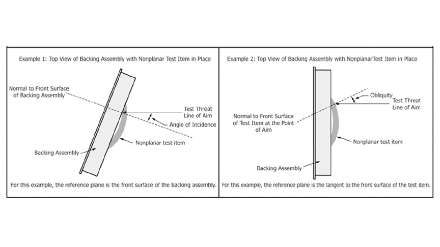
Figure 1. Examples showing angle of incidence and obliquity using a clay block backing assembly
3.1.4. applique, n. – a three-dimensional item molded from backing material that is shaped and sized for testing or conditioning a nonplanar test item. (ASTM E3005)
3.1.5. armor carrier, n. – See carrier.
3.1.6. armor panel, n. – a component of soft body armor consisting of protective materials, typically enclosed in a panel cover. See ballistic panel, blunt impact panel, stab panel. See also panel cover. (ASTM E3005)
3.1.7. backface deformation (BFD), n. – the indentation in the backing material caused by a projectile impact on the test item during testing. Synonymous with backface signature. (ASTM E3005)
3.1.8. backing assembly, n. – a backing fixture filled with backing material. For example, a clay block is a type of backing assembly. (ASTM E3005)
3.1.9. ballistic limit, n. – a measure of an item’s ballistic resistance to complete penetration expressed as a velocity associated with some probability of perforation. (ASTM E3005)
NOTE: The item may be a test item, material, shoot pack, body armor, or other ballistic-resistant product.
3.1.10. ballistic panel, n. – a type of armor panel intended to provide ballistic resistance. (ASTM E3005)
3.1.11. ballistic resistance, n. – a characteristic of protective equipment or materials describing their ability to provide protection from projectiles. (ASTM E3005)
3.1.12. body armor, n. – an item of personal protective equipment intended to protect the wearer from threats that may include ballistic threats, stabbing, fragmentation, or blunt impact. (ASTM E3005)
3.1.13. bullet, n. – a projectile fired from a firearm or testing apparatus. (ASTM E3005)
NOTE: The SAAMI definition considers bullets to be projectiles fired from rifled barrels, which differentiates bullets from shot, slugs, fragment simulators, and other projectiles.
3.1.14. carrier, n. – a garment whose primary purpose is to retain the armor panel(s) or plate(s) and provide a means of supporting and securing the armor panel(s) or plate(s) to the wearer. (ASTM E3005)
3.1.15. clay block, n. – a type of backing assembly in which the backing material is Roma Plastilina #1® modeling clay. (ASTM E3005)
3.1.16. conditioning, n. – a process that exposes an item, prior to testing, to a specified controlled environment or physical stresses, or both. (ASTM E3005)
3.1.17. controlled ambient, n. – conditions with temperature of 20.0 °C ± 5.6 °C (68 °F ± 10°F) and 50% ± 20% relative humidity (RH). (ASTM E3005)
3.1.18. fair hit, n. – a test threat impact (on a test item) that meets all specified requirements in a particular test method. (ASTM E3005)
3.1.19. hard armor, n. – an item of personal protective equipment that is constructed of rigid materials and is intended to protect the wearer from threats that may include ballistic threats, stabbing, fragmentation, or blunt impact, or combinations thereof; synonymous with hard armor plate and plate. (ASTM E3005)
3.1.20. in conjunction with armor, n. – soft or hard armor that is designed to provide a specific level of ballistic protection only when layered with a specified model(s) of body armor. (ASTM E3005)
3.1.21. insert, n. – a removable unit of protective material (soft armor or hard armor) intended to be placed into a special pocket on a carrier to enhance protection in a localized area. (ASTM E3005)
3.1.22. nonplanar, adj. – having features that would prevent the test item from making full contact with a flat surface; typically used to describe curved plates and armor designed for female wearers. (ASTM E3005)
3.1.23. obliquity, n. – the angle between the test threat line of aim and the line normal to a reference plane based on features of the test item at the point of aim. (Adapted from MIL-STD-3027.) See also angle of incidence. (ASTM E3005)
NOTE: Some standards have used the terms angle of incidence and obliquity as synonyms, but in this standard, they are defined differently. Figure 1 provides examples to aid in visualizing the difference between angle of incidence and obliquity.
3.1.24. over velocity, n. – velocity that is greater than the upper limit of a specified range. (ASTM E3005)
3.1.25. panel cover, n. – a covering, typically nonremovable, that encloses the protective materials and protects them from environmental factors, such as moisture, ultraviolet light, debris, and dust. (ASTM E3005)
3.1.26. partial penetration (PP), n. – any result of a test threat impact that is not a complete penetration; synonymous with stop. (ASTM E3005)
3.1.27. receptor, n. – film or paper of a specified abrasiveness onto which coatings (for example, ink or protective coating) removed from the specimen are deposited during the abrasion test. (ASTM D5264)
3.1.28. shot-to-edge distance, n. – the distance from the center of the projectile impact to the nearest test item edge. (ASTM E3005) For soft armor, the test item edge shall be the edge of the ballistic material. For hard armor, the test item edge shall be the outermost perimeter of the test item.
3.1.29. shot-to-shot distance, n. – the distance from the center of the projectile impact to the center of any other projectile impact on the test item. (ASTM E3005)
3.1.30. soft armor, n. – an item of personal protective equipment constructed of pliable/flexible materials intended to protect the wearer from threats that may include ballistic threats, stabbing, fragmentation, or blunt impact. (ASTM E3005)
3.1.31. strike face, n. – the surface of an armor panel or plate intended to face the incoming threat. (ASTM E3005)
3.1.32. test item, n. – a single article intended for testing. (ASTM E3005) NOTE: Examples may include one panel, one plate, or one shoot pack.
3.1.33. test series, n. – the set of all shots necessary to obtain the required number of fair hits on a single test item or the set of all shots necessary over multiple test items to generate the required data. (ASTM E3005)
3.1.34. test threat, n. – the projectile, edged blade, spike, or other object that is used in laboratory testing to impact the test item at a specific velocity or energy to assess performance of body armor. (ASTM E3005)
3.1.35. under velocity, n. – velocity that is less than the lower limit of a specified range. (ASTM E3005)
3.1.36. unfair hit, n. – a test threat impact that does not meet the specified requirements in a particular test method for impact location and spacing, velocity, obliquity, or yaw. (ASTM E3005)
3.1.37. Vx, n. – the velocity at which x% of the impacts by a specified test threat are expected to completely penetrate nominally identical test items when tested according to a specified test method. (ASTM E3005)
3.1.38. V0, n. – the maximum velocity at which 0% of the impacts by a specified test threat are expected to completely penetrate nominally identical test items when tested according to a specified test method. (ASTM E3005)
3.1.39. V05, n. – the velocity at which 5% of the impacts by a specified test threat are expected to completely penetrate nominally identical test items when tested according to a specified test method. (ASTM E3005)
3.1.40. V50, n. – the velocity at which 50% of the impacts by a specified test threat are expected to completely penetrate nominally identical test items when tested according to a specified test method. (ASTM E3005)
3.1.41. wear face, n. – the surface of an armor panel or plate that is intended to be placed against or proximal to the wearer’s body. (ASTM E3005)
3.1.42. yaw, n. – the angular deviation between the projectile’s axis of symmetry and its line of travel. (ASTM E3005)
3.2. Terms and definitions specific to this NIJ standard
3.2.1. armor model, n. – synonymous with model.
3.2.2. ballistic layup, n. – the specific ballistic materials, and their stitching, order, and orientation, of the ballistic-resistant item under consideration. Ballistic layup does not include shaping features for nonplanar armor.
3.2.3. complete penetration (CP), n. – the result of a test threat impact if one or more of the following conditions are met:
(1) any portion of a test threat or a fragment of a test threat passes through the wear face of the test item.
(2) the test threat is visible from the wear face of the test item.
(3) a hole is created through the test item by the test threat.
(4) for soft armor, any portion of a test threat or a fragment of a test threat is embedded in or passes into the backing material directly behind the test item.
(5) for hard armor, any portion of a test threat, a fragment of a test threat, or a fragment of the test item is embedded in or passes into the backing material directly behind the test item.
3.2.4. crown, n. – location of the highest point of a plate, at the intersection of multiple different curvatures.
NOTE: Novel and innovative designs (such as those for females) may include multiple high points and complex curvatures.
3.2.5. label, n. – a material applied to a product and containing information about the product.
3.2.6. label assembly, n. – the label itself and any clear plastic laminate that will be used to protect the label.
3.2.7. label system, n. – the label assembly and the substrate to which it is applied.
3.2.8. model, n. – the manufacturer’s design, with unique specifications and characteristics, of a particular item.
3.2.9. planar, adj. – two-dimensional in quality such that the test item can make full contact with a flat surface.
3.2.10. substrate, n. – the material identical to the external surface of the production body armor to which the label will be affixed. In soft armor, this will typically be the ballistic panel cover material. In some hard armors, the substrate will be the plate material itself. In other hard armors, the substrate will be the plate wrap material or the “sprayed-on liner” covering material.
3.2.11. supplier, n. – the party that is responsible for ensuring that products meet and, if applicable, continue to meet, the requirements on which the NIJ certification is based.
4. Test Threats, Equipment, and Materials
4.1. Test threats
4.1.1. The test threats shall be as specified in NIJ Standard 0123.00, Specification for NIJ Ballistic Protection Levels and Associated Test Threats.
4.2. Test range
4.2.1. The test range shall meet the requirements of ASTM E3062, including the temperature and humidity requirements.
4.2.2. No firearms shall be used for testing.
4.3. Conditioning equipment
4.3.1. Equipment for soft armor test item conditioning by tumbling shall meet the requirements described in ASTM E3192, Section 6.
4.3.2. Equipment for soft armor test item conditioning by submersion shall meet the requirements described in Appendix A: Soft Armor Conditioning by Submersion.
4.3.3. Equipment for hard armor test item conditioning by submersion shall meet the requirements described in ASTM E3112, Section 9.7.1.
4.4.2. The clay verification equipment shall be as specified in ASTM E3004, with the modifications listed below.
4.4.2.1. When verifying the backing assembly, the spherical clay-verification impactor specified in ASTM E3004, Section 5.1.6, shall be used, and the test setup shall be as specified in ASTM E3004, Section 5.1.10.
4.4.2.2. The template for marking verification drop locations shall meet the requirements of ASTM E3004, Section 5.1.8, with two additional locations positioned on the 203 mm (8 in.) radius circle, with each respective 60 and 120 degrees from the first location on the 203 mm (8 in.) radius circle. See Appendix B: Modifications to the Procedures of ASTM E3004 and Additional Requirements, Figure B1.1 for the template.
4.5. Yaw measurement equipment
4.6.1. Equipment for measuring BFD shall meet the requirements of ASTM E3068, Section 6.
5. NIJ Ballistic Protection Levels
5.1. Soft armor protection levels5.1.1. For a soft armor model being submitted for testing to this standard, the supplier shall declare to the test laboratory the intended protection level.
5.1.2. The protection levels for soft armor are NIJ HG1 and NIJ HG2 as specified in NIJ Standard 0123.00, Specification for NIJ Ballistic Protection Levels and Associated Test Threats.
5.2. Hard armor protection levels
5.2.1. For a hard armor model being submitted for testing to this standard, the supplier shall declare to the test laboratory the intended protection level.
5.2.2. The protection levels for hard armor are NIJ RF1, NIJ RF2, and NIJ RF3 as specified in NIJ Standard 0123.00, Specification for NIJ Ballistic Protection Levels and Associated Test Threats.
6. Armor Ballistic Performance Requirements
6.1. Perforation-backface deformation (P-BFD) performance requirements6.1.1. The P-BFD performance requirements are applicable to soft armor and hard armor, including in conjunction with (ICW) hard armor.
6.1.2. Each test item shall be tested as specified in the appropriate sections of this NIJ standard.
6.1.2.1. Each test item shall withstand the required number of fair hits and shall experience no complete penetrations at or below the reference velocity + 30 ft/s (+ 9.1 m/s).
6.1.2.2. Any complete penetration of a fair hit constitutes a failure.
6.1.3. BFD measurements shall be taken for: (1) soft armor test items conditioned by submersion and (2) hard armor test items conditioned by the hard armor conditioning procedure.
6.1.3.1. Either of the following two conditions shall be met:
1) Each individual BFD measurement (BFDi) ≤ 44.0 mm
or
2) (44.0 mm ≤ BFDi ≤ 50.0 mm) and (BFDave + k1s ≤ 44.0 mm)
BFDave is obtained by taking the average of all recorded fair hit BFDi measurements, at full precision, for test items of that particular model, size, conditioning status, and test threat, followed by rounding the result to the nearest
0.1 mm. s is the sample standard deviation. For explanations and calculations for BFDave, see Appendix C: BFD Measurements.
6.1.3.1.1. A BFDi measurement greater than 50.0 mm shall be considered a failure.
6.1.4. BFD measurements shall be taken for soft armor test items conditioned by tumbling. Those BFD measurements shall be recorded.
NOTE: There is no pass/fail BFD measurement requirement for test items conditioned by tumbling.
6.2. Ballistic limit performance requirements
6.2.1. The ballistic limit performance requirements are applicable to soft armor and hard armor, including in conjunction with (ICW) hard armor.
6.2.2. Each test item shall be tested as specified in the appropriate section of this NIJ standard.
7. Soft Armor Requirements and Allocation of Test Items for Conditioning and Testing
7.1. Soft armor test item sizes
The test items shall be sized according to the templates in Appendix E: Test Item Size Templates.
7.1.1. The supplier selects the templates to be used based on the range of sizes over which the armor model will be produced.
7.1.1.1. A portion of the test items shall be of the larger size and conform to one of the size templates in Appendix E: Test Item Size Templates. The remaining test items shall be a smaller size and conform to a different and smaller size template in Appendix E: Test Item Size Templates. (See Table 1 and Table 2.)
NOTE: The NIJ Compliance Testing Program (CTP) requires that the smaller size be NIJ-C-1 and the larger size be NIJ-C-5. Nonplanar test items will be tested using an appropriate applique as described in Appendix G.4.
7.1.2. For planar test items, half of the test items of each size shall be front panels with a neck scoop, as shown on the relevant test item size template.
7.1.3. All nonplanar test items shall be front panels with a neck scoop, as shown on the relevant test item size template.
7.1.3.1. For nonplanar test items, the supplier shall provide a dimensioned diagram for each size of test item indicating the location of stitches, seams, folds, and other shaping features.
7.2. Soft armor test item quantity requirements
7.2.1. For testing soft armor with planar panels, a total of 62 test items is required. See Table 1 for how the test items are to be used. The test item details are described below:
7.2.1.1. 40 larger test items: 20 test items with neck scoop and 20 test items without neck scoop.
7.2.1.2. 22 smaller test items: 14 test items with neck scoop, and 8 test items without neck scoop.
7.2.2.2. 48 smaller test items: 40 test items with neck scoop, and 8 test items without neck scoop.
7.2.3. For testing soft armor with nonplanar front panels, a total of 45 test items is required when the planar panel of the same ballistic layup has previously been tested and certified by NIJ. See Table 2 for how the test items are to be used.The test item details are described below:
7.2.3.1. 19 larger test items: All test items with neck scoop.
7.2.3.2. 26 smaller test items: All test items with neck scoop.
7.3. Soft armor test item allocation
7.3.1. Table 1 provides a summary of how each planar test item shall be allocated for conditioning and testing.
7.3.2. When testing soft armor with nonplanar front panels, Table 2 provides a summary of how each test item shall be allocated for conditioning and testing.
7.3.3. All test items shall be conditioned at controlled ambient for at least 24 hours prior to submersion.
7.3.4. All test items to be conditioned by tumbling (for both P-BFD and Ballistic Limit testing) shall be conditioned simultaneously in a single tumbler.
7.3.5. Figure 2 provides further details regarding the allocation and utilization of planar test items.
7.3.6. Figure 3 provides further details regarding the allocation and utilization of nonplanar test items.
7.4. Soft armor test item workmanship and construction requirements
7.4.1. Each test item shall be free from evidence of inferior workmanship or material defects, such as wrinkles, blisters, fabric tears, fraying, unintended folds/creases, or discoloration of materials or stitching.
7.4.2. The stitching for each test item shall be consistent and secure.
7.4.3. There shall be no variation in construction details between individual test items.
7.4.4. All test items shall be identical in appearance, materials, and manner of construction, including stitch size and location, as appropriate for the sizes submitted.
7.5. Soft armor test item label requirements
7.5.1. The label shall be permanently attached to the panel cover of the test item and shall meet the requirements below.
7.5.1.1. The label text shall be in a readable typeface and font size, and the content shall be as specified in Appendix F: Label Requirements, Section F.1: Label Content Requirements.
7.5.1.2. This label shall match, in materials, manner of construction, printing, and ink(s), the label on a production armor.
7.5.1.3. The labels for every test item conditioned by tumbling shall be evaluated following tumbling.
7.5.1.3.1. Each label shall remain legible and attached to the test item in its original position.
7.5.1.3.2. No more than one inch (25.4 mm) of separation of any label edge from the test item is allowed.
7.5.2. Failure of a label to meet the above requirements is not considered a failure of the armor model. In the event of a label failing to meet these requirements, a case-by-case evaluation will be made by the NIJ CTP.
7.6. Soft armor test item carrier requirements
7.6.1. Test items shall be submitted with carriers that are made from cotton or poly-cotton fabric having an areal density of less than or equal to 250 g/m2 (7.4 oz/yd2).
7.6.1.1. If the manufacturer chooses to submit a carrier that does not meet the above requirement, then the carrier becomes part of the unique design and construction of the armor model and cannot be changed in production.
NOTE: It is recommended that the manufacturer contact the NIJ CTP prior to submitting test items to the laboratory.
7.6.2. Carriers for test items that will undergo conditioning by tumbling shall not have strapping, strapping attachment points, or any accessory mounting points.
| Size and Quantity of Test Items | Conditioning and Quantity of Test Items | Quantity of Test Items for Each Test | |||
| Larger size 40 test items: 20 test items with neck scoop, 20 test items without neck scoop |
Conditioning at controlled ambient for at least 24 hours followed by submersion, per Appendix A | 8 |
P-BFD Test |
With neck scoop | 4 |
| Without neck scoop | 4 | ||||
| Conditioning at controlled ambient for at least 24 hours followed by tumbling, per ASTM | 10 | P-BFD Test |
With neck scoop | 2 | |
| Without neck scoop | 2 | ||||
| Ballistic Limit Test |
With neck scoop | 2 | |||
| Without neck scoop | 2 | ||||
Spares |
With neck scoop | 1 | |||
| Without neck scoop | 1 | ||||
| Conditioning at controlled ambient for at least 24 hours | 22 | Ballistic Limit Test | With neck scoop | 10 | |
| Without neck scoop | 10 | ||||
| Spares | With neck scoop | 1 | |||
| Without neck scoop | 1 | ||||
| Smaller size 22 test items: 14 test items with neck scoop, 8 test items without neck scoop |
Conditioning at controlled ambient for at least 24 hours followed by | 12 | P-BFD Test | With neck scoop | 8 |
| Without neck scoop | 4 | ||||
| Conditioning at controlled ambient for at least 24 hours followed by tumbling, per ASTM E3192 | 8 | P-BFD Test | With neck scoop | 4 | |
| Without neck scoop | 2 | ||||
| Spares | With neck scoop | 1 | |||
| Without neck scoop | 1 | ||||
| Conditioning at controlled ambient for at least 24 | 2 | Spares | With neck scoop | 1 | |
| Without neck scoop | 1 | ||||
Note: “With neck scoop” is equivalent to “front panel,” and “without neck scoop” is equivalent to “rear panel.”
| Size and Quantity of Test Items | Conditioning and Quantity of Test Items |
Quantity of Test Items for Each Test |
|||
|
Larger size 19 test items: All test items with neck scoop |
Conditioning at controlled ambient for at least 24 hours followed by submersion, per Appendix A | 8 | P-BFD Test | With neck scoop | 8 |
|
Conditioning at controlled ambient for at |
10 |
P-BFD Test | With neck scoop | 4 | |
|
least 24 hours followed by tumbling, per ASTM E3192 |
P-BFD Test | With neck scoop | 6 | ||
|
Conditioning at controlled ambient for at least 24 hours |
1 | Spare | With neck scoop | 1 | |
|
Smaller size 26 test items: All test items with neck scoop |
Conditioning at controlled ambient for at least 24 hours followed by submersion, per Appendix A | 16 | P-BFD Test | With neck scoop | 16 |
| Conditioning at controlled ambient for at least 24 hours followed by tumbling, per ASTM E3192 |
9 |
P-BFD Test | With neck scoop | 8 | |
| Spare | With neck scoop | 1 | |||
| Conditioning at controlled ambient for at least 24 hours | 1 | Spare | With neck scoop | 1 | |
Note: “With neck scoop” is equivalent to “front panel.”
8. Soft Armor Test Item Examination
8.1. Verify the group of test items are of the correct model and correct quantity and sizes.
8.2. Examine the group of test items for variations in appearance.
8.3. Weigh each test item.
8.4. Examine the label of a single spare test item to determine whether requirements of
Appendix F: Label Requirements, Section F.1: Label Content Requirements, are met.
8.5. Prior to submersion or tumbling, photograph at least one test item of each size. For the photograph, the test item shall be lying on a flat surface and shall have a scale (i.e., ruler) visible.
8.6. Following tumbling, evaluate the label of each test item to determine if the label remains legible and adhered to the test item.
8.7. Following ballistic testing, perform the steps below:
8.7.1. Horizontally slit only the test item panel cover with a razor blade near the bottom of the test item and remove the ballistic panel from its cover.
8.7.2. Document any evidence of inferior workmanship or material defects.
8.7.3. Document the construction of the ballistic panel (e.g., layer count, material description, stitching).
8.7.4. Examine the construction of each test item to determine whether the requirements of Sections 7.4.2 through 7.4.4 are met.
8.7.5. After inspecting, reinsert the ballistic panel in its panel cover in the correct orientation.
8.8. Document the relevant details for each test item.
9. Soft Armor Ballistic Test Requirements and Procedures
9.1. Soft armor shots required: planar and nonplanar
9.1.1. A complete P-BFD test series and Ballistic Limit test series consists of the total required number of fair hits accumulated on the required number of test items for each of the specified test threats, as shown in Figure 2 for planar test items or Figure 3 for nonplanar test items.
9.1.1.1. The number of shots shown in Figures 2 and 3 represent the required number of fair hits.
NOTE: Additional shots may be necessary to achieve the required number of fair hits.
9.1.1.2. Each test item shall be subjected to the number of fair hits specified in Figure 2 or Figure 3, as appropriate, using the specified test threat.
9.2. Soft armor P-BFD test requirements
9.2.1. Seven P-BFD shots per test item are required as specified in ASTM E3107.
9.2.2. The fair hit requirements shall be as specified in ASTM E3107, Section 9.3, with the following exceptions:
9.2.2.1. The minimum shot-to-edge distance may be decreased at the request of the supplier.
9.2.2.2. The minimum shot-to-edge distance shall not be greater than 3.0 in (76 mm) for the greater mass test threat and shall not be greater than 2.0 in (51 mm) for the lesser mass test threat.
9.2.2.3. When the measured velocity is not within ± 30 ft/s (± 9.1 m/s) of the reference velocity, but all other requirements are met, the shot shall be considered a fair hit if either:
(1) the velocity is less than the minimum allowed and the shot results in a complete penetration (CP), a BFD measurement is greater than 44.0 mm, or both
or
(2) the velocity is greater than the maximum allowed and results in a partial penetration (PP) and BFD measurement less than or equal to 44.0 mm.
9.2.3. A test item that is impacted with an over-velocity shot and subsequently impacted with a fair hit that completely penetrates or results in a BFD measurement greater than 50.0 mm shall be replaced with a spare test item. This occurrence and the results shall be documented. These shots shall not be included in the data set for calculations. The test series shall be repeated on the spare test item.
9.2.4. A test item that is impacted with an over-velocity shot may be replaced with a spare test item when the following two conditions are met:
1) the over velocity shot results in a PP with a BFD measurement less than 44.0 mm and
2) another subsequent shot in the test series is a fair hit with a BFD measurement greater than 44.0 mm but less than 50.0 mm
9.2.4.1. If the test item is replaced per the conditions above, this occurrence and the results shall be documented. The shots shall not be included in the data set for calculations. The test series shall be repeated on the spare test item.
NOTE: Despite being a passing result, there is concern that the over-velocity would result in a greater dispersion in the BFD data set. See Appendix C: BFD Measurements.
9.2.5. When a shot is determined to be an unfair hit, additional attempts shall be made to obtain a fair hit on the same test item.
9.2.5.1. The number of shots taken on a single test item shall not exceed nine. If this requirement cannot be met, the test series shall be repeated on a spare test item of the same size. This occurrence and the results shall be documented. The shots taken on the spare test item shall be included in the data set for calculations. The shots taken on the original test item shall not be included in the data set for calculations.
9.2.6. For shot 7 on a front panel, if any portion of a test threat or a fragment of a test threat is embedded in or passes into any area of the backing material, that shall be considered a CP.
NOTE: This is an exception to the definition of a CP on soft armor from Section
3.2.3 of this NIJ standard that applies only to shot 7 at the neck of a front panel.
9.2.7. The duration of the ballistic testing of each test item shall be no more than 30 minutes from the time the first shot is fired until the last shot is fired.
9.2.7.1. If the time limit is exceeded, the test series shall be repeated on a spare test item. This occurrence and the results shall be documented. The shots taken on the spare test item shall be included in the data set for calculations. The shots taken on the original test item shall not be included in the data set for calculations.
9.2.8. Ballistic testing of each test item conditioned by submersion shall begin within 15 minutes of removal from the water bath described in Appendix A: Soft Armor Conditioning by Submersion (including the 10-minute drying time).
9.2.9. BFD measurements shall be taken on shots 1, 2, and 3 for each test item, and the measurand shall be as defined in ASTM E3068, Section 7.
9.2.9.1. BFD measurements for planar test items shall be performed according to ASTM E3068, Section 8.
9.2.9.2. BFD measurements for nonplanar test items shall be performed according to ASTM E3068, Section 9.
9.2.10. The angle of incidence for each shot shall be as specified in ASTM E3107, Section 11.2.
9.3. Soft armor P-BFD test procedure for planar test items
9.3.1. The steps of this procedure are detailed as a flowchart in Figure H.1 of Appendix H: Flowcharts for Testing, and summarized below.
9.3.2. For test items to be conditioned by submersion, mark shot locations on the test items per ASTM E3107, Section 11.2, prior to conditioning.
9.3.2.1. For test items having construction features, the locations of shots 4, 5, and 6 shall be adjusted to exploit the perceived weaknesses of the test item.
9.3.2.2. Condition the test items as specified in Section 7.3 and Table 1 or Table 2 of this NIJ standard.
9.3.3. For test items to be conditioned by tumbling, condition the test items as specified in Section 7.3 and Table 1 or Table 2 of this NIJ standard.
9.3.3.1. Following conditioning, mark shot locations on each test item per ASTM E3107, Section 11.2.
9.3.3.1.1. For test items having construction features, the locations of shots 4, 5, and 6 shall be adjusted to exploit perceived weaknesses of the test item.
9.3.4. Prepare and verify the clay block as specified in ASTM E3004, Section 6.3, with the modifications listed in Appendix B, Section B.2: Modifications to ASTM E3004, Section 6.3, Clay Block Verification Procedure: Prior to Ballistic Testing.
9.3.4.1. If the clay block meets the acceptance criteria, then repair the clay block according to ASTM E3004, Section 6.4, Clay Block Repair.
9.3.4.2. If the clay block does not meet the acceptance criteria, then follow the steps of ASTM E3004, Section 6.5, Clay Blocks That Fail to Meet the Acceptance Criteria, or select another clay block and repeat 9.3.4.
9.3.5. Position the clay block for shooting, and place the test item on the clay block per ASTM E3107, Section 10.
9.3.6. Perform the steps of ASTM E3107, Section 11.3, taking shots in this order: 1, 2, 3, 7, 4, 5, 6.
9.3.6.1. Document the result (i.e., CP or PP) and other required data.
9.3.6.2. Determine whether the shot was a fair hit and take appropriate actions.
9.3.6.3. Following each of shots 1, 2, and 3, remove the test item and follow the procedures of ASTM E3068, Section 8 for planar armor.
9.3.7. If there are additional test items in the test series, perform the procedure of ASTM E3004, Section 6.6, with the modifications listed in Appendix B, Section B.3: Modifications to ASTM E3004, Section 6.6, Clay Block Verification Procedure: Between Test Items, and repeat the above procedure on another test item.
9.3.8. After the final test item in the test series has been tested, perform the procedure of ASTM E3004, Section 6.7, with the modifications listed in Appendix B, Section B.4: Modifications to ASTM E3004, Section 6.7, Clay Block Verification Procedure: After Final Shot on Clay Block.
9.4. Soft armor P-BFD test procedure for nonplanar test items
9.4.1. The steps of this procedure are detailed as a flowchart in Figure H.1 of Appendix H: Flowcharts for Testing, and summarized below.
9.4.1.1. These steps apply only to nonplanar front panels. The construction of the armor model shall have been fully tested as planar armor prior to taking the steps of this section.
9.4.2. For test items to be conditioned by submersion, mark shot locations on the test items per Appendix G: Guidance for P-BFD Testing of Soft Armor Designed for Female Wearers of this NIJ standard, prior to conditioning.
9.4.2.1. For smaller test items, shots 1, 2, and 3 shall be marked on one test item, and shots 4, 5, 6, and 7 shall be marked on another.
9.4.2.2. Condition the test items as specified in Section 7.3 and Table 1 or Table 2 of this NIJ standard.
9.4.3. For test items to be conditioned by tumbling, condition the test items as specified in Section 7.3 and Table 1 or Table 2 of this NIJ standard.
9.4.3.1. Following conditioning, mark shot locations on each test item per Appendix G: Guidance for P-BFD Testing of Soft Armor Designed for Female Wearers, of this NIJ standard.
9.4.3.1.1. For smaller test items, shots 1, 2, and 3 shall be marked on one test item, and shots 4, 5, 6, and 7 shall be marked on another.
9.4.4. For shots 1, 2, and 3 on nonplanar soft test items, place the test item on the clay block and flatten it as much as possible.
9.4.5. For shots 4, 5, 6, and 7 on nonplanar soft armor test items, construct a suitable applique to fill the void between the test item and the clay block.
9.4.5.1. Follow the procedure in Appendix G: Guidance for P-BFD Testing of Soft Armor Designed for Female Wearers of this NIJ standard to create the applique.
9.4.5.2. Each applique shall be formed using clay that has been temperature conditioned as specified in ASTM E3004.
9.4.5.3. Each applique shall be stored, until needed for testing, in a chamber having temperature conditions as specified in ASTM E3004.
9.4.6. Prepare and verify the clay block as specified in ASTM E3004, Section 6.3, with the modifications listed in Appendix B, Section B.2: Modifications to ASTM E3004, Section 6.3, Clay Block Verification Procedure: Prior to Ballistic Testing.
9.4.6.1. If the clay block meets the acceptance criteria, then repair the clay block according to ASTM E3004, Section 6.4, Clay Block Repair.
9.4.6.2. If the clay block does not meet the acceptance criteria, then follow the steps of ASTM E3004, Section 6.5, Clay Blocks That Fail to Meet the Acceptance Criteria, or select another clay block and repeat 9.4.5.
9.4.7. For shots 1, 2, and 3, position the clay block (without applique) for shooting and place the test item on the clay block per ASTM E3107, Section 10.
9.4.8. For shots 4, 5, 6, and 7, affix the applique to the clay block, position the clay block for shooting, and place the test item on the clay block per ASTM E3107, Section 10, aligning the test item with the applique.
9.4.9. Perform the steps of ASTM E3107, Section 11.3, taking shots in this order: 1, 2, 3, 7, 4, 5, 6.
9.4.9.1. Document the result (i.e., CP or PP) and other required data.
9.4.9.2. Determine whether the shot was a fair hit and take appropriate actions.
9.4.9.3. Following each of shots 1, 2, and 3, remove the test item and follow the procedures of ASTM E3068, Section 9 for nonplanar armor.
9.4.10. If there are additional test items in the test series, perform the procedure of ASTM E3004, Section 6.6, with the modifications listed in Appendix B, Section B.3: Modifications to ASTM E3004, Section 6.6, Clay Block Verification Procedure: Between Test Items, and repeat the above procedure on another test item.
9.4.10.1. When conducting P-BFD testing on smaller front test items, clay block verification shall not be required after the test items that include only shots 1, 2, and 3. Please refer to Figure 2 for planar test items and Figure 3 for nonplanar test items. Clay block verification shall be conducted after all other test items are tested.
9.4.11. After the final test item in the test series has been tested, perform the procedure of ASTM E3004, Section 6.7, with the modifications listed in Appendix B, Section B.4: Modifications to ASTM E3004, Section 6.7, Clay Block Verification Procedure: After Final Shot on Clay Block.
9.5. Soft armor ballistic limit test requirements
9.5.1. The intended velocity of the first shot shall be the reference velocity for the test threat.
9.5.1.1. The actual velocity of the first shot shall be the reference velocity ±100 ft/sec (±30 m/s) for the test threat.
9.5.1.1.1. If this requirement is not met, that shot shall be considered an unfair hit and not included in the data set for ballistic limit calculations. The first shot shall be repeated on the same test item.
9.5.2. After the first shot, the velocity shall be incremented per the steps shown in Table 3. All steps shall be incremented based on the previous intended velocity (i.e., not the measured velocity).
Table 3. Velocity Increments
|
Nominal Velocity |
Incremental Velocity Value |
|
Velocity step until first reversal |
-100 ft/sec (-30 m/s) if first shot was a CP |
|
+100 ft/sec (+30 m/s) if first shot was a PP |
|
|
Velocity step until second reversal |
±75 ft/sec (± 23 m/s) depending on result of previous shot |
|
Velocity step after second reversal |
±50 ft/sec (± 15 m/s) depending on result of previous shot |
9.5.3. The test requirements of ASTM E3110, Section 9 apply.
9.5.4. The removable plywood backing on the clay block shall be removed for ballistic limit testing.
9.5.5. The fair hit requirements shall be as specified in ASTM E3110, Section 9.1, with the following exceptions:
9.5.5.1. The minimum shot-to-edge distance may be decreased at the request of the supplier.
9.5.5.2. The minimum shot-to-edge distance shall not be greater than 2.0 in (51 mm) for the lesser mass test threat and shall not be greater than 3.0 in (76 mm) for the greater mass test threat.
9.5.6. The number of shots taken on a single test item shall not exceed 15. If this requirement cannot be met, the test series shall be continued on a spare test item. This occurrence shall be documented.
9.5.7. The ballistic limit data set shall contain at least 60 PPs and at least 30 CPs. The additional outcomes may be either PPs or CPs.
9.5.7.1. When the ballistic limit is sufficiently high that achieving the velocity necessary to perforate the test item is difficult or impossible, the test laboratory shall document that this situation has occurred. In such cases, the test series will be considered acceptable when a minimum of 120 shots has been taken even if the minimum number of CPs is not achieved.
9.5.8. All shots for ballistic limit testing shall be reported. The shot information shall be reported in the order of shots fired and, at a minimum, shall include shot number, measured velocity, and shot outcome.
9.6. Soft armor ballistic limit procedure for planar test items
9.6.1. The steps of this procedure are detailed as a flowchart in Figure H.2 of Appendix H: Flowcharts for Testing, and summarized below.
9.6.2. Condition test items as specified in Section 7.3 and Table 1 or Table 2 of this NIJ standard.
9.6.2.1. Following the required conditioning procedure or sequence, mark the shot locations on each test item, following the shot spacing requirements of Section 9.5.5 of this NIJ standard.
9.6.2.1.1. If test item size permits, the shot locations should avoid areas where there is an overlap of ballistic material. Impacts on areas of overlap are considered fair hits and shall be documented.
9.6.3. Prepare and verify the clay block as specified in ASTM E3004, Section 6.3, with the modifications listed in Appendix B, Section B.2: Modifications to ASTM E3004, Section 6.3, Clay Block Verification Procedure: Prior to Ballistic Testing.
9.6.3.1. If the clay block meets the acceptance criteria, then repair the clay block according to ASTM E3004, Section 6.4, Clay Block Repair.
9.6.3.2. If the clay block does not meet the acceptance criteria, then follow the steps of ASTM E3004, Section 6.5, Clay Blocks That Fail to Meet the Acceptance Criteria, or select another clay block and repeat 9.6.3.
9.6.4. Position the clay block for shooting (ensuring that the plywood backing is not attached), and place the test item on the clay block.
9.6.5. Perform the steps of ASTM E3110, Section 14.
9.6.5.1. Document each shot outcome (i.e., CP or PP), the corresponding measured velocity for each shot, and other required data.
9.6.5.2. Determine whether the shot was a fair hit and take appropriate actions.
10. Hard Armor Requirements and Allocation of Test Items for Conditioning and Testing
10.1. Stand-alone hard armor and ICW hard armor10.1.1. This section applies to stand-alone hard armor and ICW hard armor.
10.1.2. For ICW hard armor, an equivalent number of soft armor test items, sized to the NIJ- C-2 template, is required.
10.1.2.1. The associated soft armor model shall be listed on the NIJ Standard 0101.07 Compliant Products List.
10.1.3. For ICW hard armor models, the soft armor carrier shall have the necessary pocket for the hard armor.
10.2. Hard armor test item quantity and size requirements
10.2.1. Either 33 or 63 test items per test threat are required for testing to NIJ RF1. The number required depends on whether the test items are specified by the supplier for three or six shots.
NOTE: There are three test threats for NIJ RF1.
10.2.2. Either 43 or 83 test items per test threat are required for testing to NIJ RF2. The number required depends on whether the test items are specified by the supplier for three or six shots.
NOTE: There are four test threats for NIJ RF2 (including the three threats for NIJ RF1).
10.2.3. 10 to 50 test items are required for testing to NIJ RF3. The number required depends on whether the test items are specified by the supplier for one, two, three, or six shots.
NOTE: There is one test threat for NIJ RF3.
10.2.4. Test items shall be no larger than 10 in x 12 in (254 mm x 305 mm). All test items shall be identically sized.
10.2.4.1. For all nonplanar test items, the supplier shall provide a dimensioned diagram for the test items indicating the crown location(s).
10.3. Hard armor test item workmanship and construction requirements
10.3.1. Each test item shall be free from evidence of inferior workmanship or material defects, such as uneven coatings or thicknesses of materials, wrinkles, blisters, cracks, fabric tears, fraying, crazing, and chipped or sharp edges.
10.3.2. There shall be no variation in construction details between individual test items.
10.3.3. All test items shall be identical in appearance, materials, and manner of construction, including the outside perimeter and shape of the test item.
10.4. Hard armor test item label requirements
10.4.1. The label shall be permanently attached to the exterior of the test item and shall meet the requirements below.
10.4.1.1. The label text shall be in a readable typeface and font size, and the content shall be as specified in Appendix F, Section F.1: Label Content Requirements.
10.4.1.2. This label shall match — in materials, manner of construction, printing, and ink(s) — the label on a production armor.
10.4.1.3. The labels for every test item shall be evaluated following conditioning, and each label shall remain legible and attached to the test item in its original position. No more than one inch (25.4 mm) of separation of any label edge from the test item is allowed.
10.5. Hard armor test item allocation for conditioning and testing
10.5.1. A summary of how hard armor test items shall be allocated for conditioning and testing is shown in Table 4.
10.5.2. All test items shall be conditioned at controlled ambient for at least 24 hours prior to subsequent hard armor conditioning or conditioning by submersion.
10.5.3. All test items, except for one archive test item, shall be subjected to the hard armor conditioning procedures specified in ASTM E3078, Sections 13 and 14. Test items for P-BFD testing shall subsequently be conditioned by submersion per ASTM E3112, Section 9.7.2.
10.5.4. Figure 4 provides further details regarding the allocation and utilization of hard armor and ICW test items at the NIJ RF1 protection level.
10.5.5. Figure 5 provides further details regarding the allocation and utilization of hard armor and ICW test items at the NIJ RF2 protection level.
10.5.6. Figure 6 provides further details regarding the allocation and utilization of hard armor and ICW test items at the NIJ RF3 protection level.
10.5.6.1. The soft armor test items shall be conditioned by submersion, per Appendix A of this NIJ standard, prior to ballistic testing.
10.5.6.2. The combination of that soft armor and the hard armor shall then be tested as a system at a specified NIJ RF protection level.
| Protection Level and Quantity of Test Items |
Conditioning and Quantity of Test Items |
Quantity of Test Items for Each Test |
|||
NIJ RF1 |
33 or 63 |
Hard armor conditioning per ASTM 3078 followed by submersion per Appendix A | 18 or 36 | P-BFD | 18 or 36 |
| Hard armor conditioning per ASTM 3078 |
14 or 26 |
Ballistic Limit | 12 or 24 | ||
| Spare | 2 | ||||
| Conditioning at controlled ambient for at least 24 hours | 1 | Archive | 1 | ||
| NIJ RF2 |
43 or 83 |
Hard armor conditioning per ASTM 3078 followed by submersion per Appendix A | 24 or 48 | P-BFD | 24 or 48 |
| Hard armor conditioning per ASTM 3078 |
18 or 34 |
Ballistic Limit | 16 or 32 | ||
| Spare | 2 | ||||
| Conditioning at controlled ambient for at least 24 hours | 1 | Archive | 1 | ||
| NIJ RF3 | 10 to 50 | Hard armor conditioning per ASTM 3078 followed by submersion per Appendix A | 6, 12, 18, or 36 | P-BFD | 6, 12, 18, or 36 |
| Hard armor conditioning per ASTM 3078 | 3, 5, 7, or 13 | Ballistic Limit | 2, 4, 6, or 12 | ||
| Spare | 1 | ||||
| Conditioning at controlled ambient for at least 24 hours | 1 | Archive | 1 | ||
11. Hard Armor Test Item Examination Procedure
11.1. Verify the group of test items for correct quantity and sizes.
11.2. Examine the group of test items for variations in appearance.
11.3. Weigh each test item.
11.4. Examine the test item label text to determine whether the content requirements are met.
11.5. Prior to conditioning by the hard armor conditioning procedure, photograph at least one test item.
11.6. Following conditioning, examine the test items for visible damage due to conditioning and photograph any test items showing such damage.
11.7. Following ballistic testing, perform the steps below:
11.7.1. If necessary, cut open one side of the test item and peel back the cover or coating material enough to allow viewing of subcomponents.
11.7.2. Document any evidence of inferior workmanship or material defects.
11.7.3. Document the construction of the ballistic plate (e.g., material description, thickness of layered subcomponents, presence of coatings) to assess whether all test items are visually similar.
11.7.4. Examine the construction of each test item to determine whether the requirements of Sections 10.3.2 and 10.3.3 are met.
11.8. Document the relevant details for each test item
12. Hard Armor Ballistic Test Requirements and Procedures
12.1. Hard armor shots required
12.1.1. A complete P-BFD test series and Ballistic Limit test series consists of the total required number of fair hits accumulated on the required number of test items for each of the specified test threats, as shown in Figure 4 for NIJ RF1, Figure 5 for NIJ RF2, and Figure 6 for RF3.
12.1.1.1. The number of shots shown in Figures 4, 5, and 6 represent the required number of fair hits.
NOTE: Additional shots may be necessary to achieve the required number of fair hits.
12.1.2. Each test item shall be subjected to the number of fair hits specified in Figure 4, 5, or 6, as appropriate, using the specified test threat.
12.1.2.1. The supplier shall declare the number shots to be placed on a single test item in accordance with the listed options.
NOTE: NIJ allows the supplier to choose the number of shots to place on each test item. This enables a supplier to use fewer test items to achieve the required number of shots; however, the supplier assumes the risk associated with a higher number of shots.
12.2. Hard armor P-BFD test requirements
12.2.1. The fair hit requirements shall be as specified in ASTM E3107, Section 9.3, with the following exceptions:
12.2.1.1. Minimum shot-to-edge distances may be decreased at the request of the supplier.
12.2.1.2. All edge shots shall meet the shot-to-edge distance requirements but shall be located not more than the shot-to-edge distance plus 0.75 in (19 mm) from the edge of the test item.
12.2.1.3. When the measured velocity is not within ± 30 ft/s (± 9.1 m/s) of the reference velocity, but all other requirements are met, the shot shall be considered a fair hit if either:
(1) the velocity is less than the minimum allowed and the shot results in a CP, a BFD measurement is greater than 44.0 mm, or both
or
(2) the velocity is greater than the maximum allowed and results in a PP and BFD measurement less than or equal to 44.0 mm.
12.2.2. The shot placement for a 3-shot plate shall be on the test item strike face as shown in Figure 7.
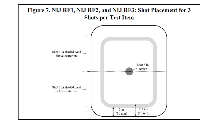
12.2.2.1. For each test item, shots 1 and 2 shall be moved to different locations within the shaded band, and shot 3 shall be placed on the center for a planar plate or on the apex of the curve in the center of the plate for a single-curve plate.
NOTE: The crown is not necessarily in the center of the plate for a multi-curve plate. Figure 8 shows an example of a multi-curve swimmer/shooters cut plate where the crown is located in the upper portion of the plate.
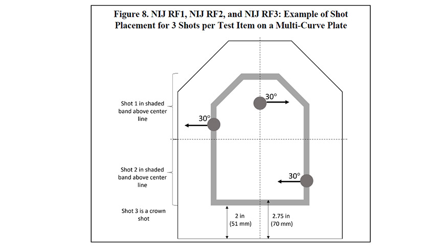
12.2.2.2. All shots shall be taken at either 0° or 30° angle of incidence. See Figures 4, 5, and 6 for specific shot angles. For a 3-shot plate with 30-degree shots, the following requirements apply:
(1) The crown shot and the next closest shot shall be angled away from each other.
(2) The remaining shot shall be angled toward the centerline.
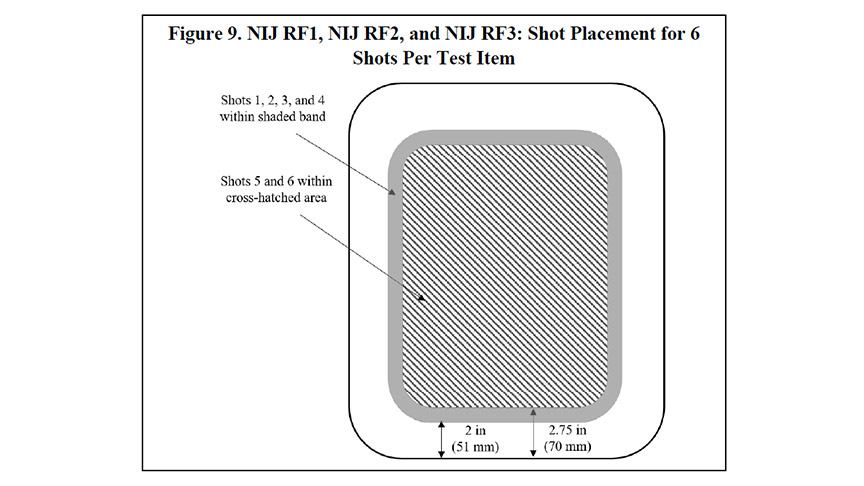
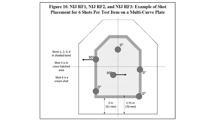
12.2.3. The shot placement for a 6-shot plate shall be on the test item strike face as shown in Figure 9.
12.2.3.1. For each test item, shots 1, 2, 3, and 4 shall be moved to different locations within the shaded band, and shots 5 and 6 shall be placed in the cross-hatched area; for a curved plate, either shot 5 or shot 6 shall be placed on the crown.
NOTE: The crown is not necessarily in the center of the plate for a multi-curve plate. Figure 10 shows an example of a multi-curve swimmer/shooters cut plate where the crown is located in the upper portion of the plate.
12.2.3.2. All shots shall be taken at either 0° or 30° angle of incidence. See Figures 4, 5, and 6 for specific shot angles. The following requirements apply:
(1) Shot 6 (crown shot) and three shots in the shaded band shall be taken at 0 degrees.
(2) Shot 5 shall be angled at 30 degrees toward the centerline, and one shot in the shaded band shall be angled at 30 degrees away from the centerline.
(3) BFD measurements shall be taken for all 0 degree shots, including the crown shot.
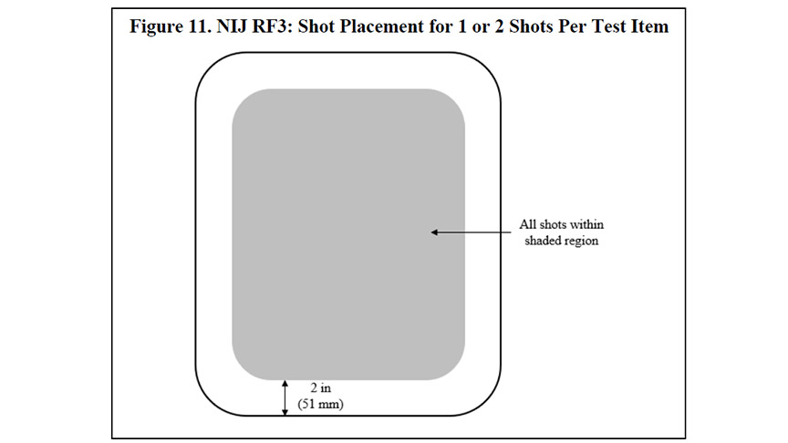
12.2.4. The shot placement for a 1-shot or 2-shot plate shall be on the test item strike face as shown in Figure 11. For a curved plate, at least 25% of the shots in the test series shall be placed on the crown
12.2.5. For test items in which the cross-sectional layup varies across the plate, the placement of shots shown in Figures 7, 9, and 11 shall be adjusted to exploit perceived weaknesses of the test item. Shot angles and number of shots may be adjusted to fully challenge the design.
12.2.6. A test item that is impacted with an over-velocity shot and subsequently impacted with a fair hit that completely penetrates or results in a BFD measurement greater than 50.0 mm shall be replaced with a spare test item. This occurrence and the results shall be documented. The shots taken on the original test item shall not be included in the data set for calculations. The shots taken on the spare test item shall be included in the data set for calculations.
12.2.7. A test item that is impacted with an over-velocity shot may be replaced with a spare test item when the following two conditions are met:
1) the over-velocity shot results in a PP with a BFD measurement less than 44.0 mm and
2) another subsequent shot in the test series is a fair hit with a BFD measurement greater than 44.0 mm but less than 50.0 mm
12.2.7.1. If the test item is replaced per the conditions above, this occurrence and the results shall be documented. The shots taken on the original test item shall not be included in the data set for calculations. The test series shall be repeated on the spare test item. The shots taken on the spare test item shall be included in the data set for calculations.
NOTE: Despite being a passing result, there is concern that the over-velocity would result in a greater dispersion in the BFD data set. See see Appendix C: BFD Measurements.
12.2.8. When a shot is determined to be an unfair hit, any preceding shots on that test item shall be included in the data set for the calculations, and this shot shall be repeated on a spare test item. The remainder of the test series shall be continued on the spare test item. This occurrence and the results shall be documented.
12.2.9. The duration of the ballistic testing of each test item shall be no more than 30 minutes from the time the first shot is fired until the last shot is fired.
12.2.9.1. If the time limit is exceeded, the test series shall be repeated on a spare test item. This occurrence and the results shall be documented. The shots taken on the original test item shall not be included in the data set for calculations. The shots taken on the spare test item shall be included in the data set for calculations.
12.2.10. The occurrence of side spalling from angled edge shots shall be documented but is not a failure.
12.3.1.1. BFD measurements for planar test items shall be performed according to ASTM E3068, Section 8.
12.3.1.2. BFD measurements for nonplanar test items shall be performed according to ASTM E3068, Section 9.
12.3.2. BFD measurements shall be taken on each test item as specified below:
12.3.2.1. When taking one shot per test item, BFD measurement shall be made on shot 1.
12.3.2.2. When taking two or three shots per test item, BFD measurements shall be made on shots 1 and 2.
12.3.2.3. When taking six shots per test item, BFD measurements shall be made on shot 6 and three of the shots within the shaded band.
12.4. Hard armor P-BFD test procedure for planar and nonplanar test items
12.4.1. The steps of this procedure are detailed as a flowchart in Figure H.3 of Appendix H: Flowcharts for Testing, and summarized below.
12.4.2. Condition the test items as specified in Section 10.5 and Table 4 of this NIJ standard.
12.4.3. Mark shot locations on the test items per this NIJ standard, Section 12.2.2 through
12.2.5 (as appropriate), ensuring that shot locations meet the shot spacing requirements.
12.4.4. For nonplanar hard armor, follow the procedure in ASTM E3107, Section 12.3 to create the applique.
12.4.4.1. Each applique shall be formed using clay that has been temperature conditioned as specified in ASTM E3004.
12.4.4.2. Each applique shall be stored, until needed for testing, in a chamber having temperature conditions as specified in ASTM E3004.
12.4.5. Prepare and verify the clay block as specified in ASTM E3004, Section 6.3, with the modifications listed in Appendix B, Section B.2: Modifications to ASTM E3004, Section 6.3, Clay Block Verification Procedure: Prior to Ballistic Testing.
12.4.5.1. If the clay block meets the acceptance criteria, then repair the clay block according to ASTM E3004, Section 6.4, Clay Block Repair.
12.4.5.2. If the clay block does not meet the acceptance criteria, then follow the steps of ASTM E3004, Section 6.5 Clay Blocks That Fail to Meet the Acceptance Criteria, or select another clay block and repeat 12.4.4.
12.4.6. Position the clay block for shooting, and mount the test item and applique (as needed) on the clay block as specified in ASTM E3107, Section 12.
12.4.7. Perform the steps of ASTM E3107, Section 13.
12.4.7.1. Document the result (i.e., CP or PP) and other required data.
12.4.7.2. Determine whether the shot was a fair hit according to Section 12.2 of this NIJ standard and take appropriate actions.
12.4.7.3. Following each shot for which BFD is to be measured, remove the test item and follow the procedures of ASTM E3068, Section 8 for planar armor or Section 9 for nonplanar armor.
12.4.8. If there are additional test items in the test series, perform the procedure of ASTM E3004, Section 6.6, with the modifications listed in Appendix B, Section B.3: Modifications to ASTM E3004, Section 6.6, Clay Block Verification Procedure: Between Test Items, and repeat the above procedure on another test item.
12.4.8.1. When conducting RF1 or RF2 testing using three shots per item, clay block verification shall be required only after six shots have been fired (i.e., after every other test item). The six shots shall be fired in consecutive order using the same clay block. Please refer to “Option 2” in Figure 4 and Figure 5. Clay block verification shall be conducted after all other test items are tested.
12.4.8.2. When conducting RF3 testing using less than six shots per test item, clay block verification shall be required only after six shots have been fired. The six shots shall be fired in consecutive order using the same clay block. Please refer to “Option 2,” “Option 3,” and “Option 4” in Figure 6. Clay block verification shall be conducted after all other test items are tested.
12.4.9. After the final test item in the test series has been tested, perform the procedure of ASTM E3004, Section 6.7, with the modifications listed in Appendix B, Section B.4: Modifications to ASTM E3004, Section 6.7, Clay Block Verification Procedure: After Final Shot on Clay Block.
12.5. Hard armor ballistic limit test requirements
12.5.1. The ballistic limit test requirements from Section 9.5 of this NIJ standard apply to hard armor.
12.5.2. The ballistic limit data set for NIJ RF1 and NIJ RF2 shall contain at least six CPs and at least 12 PPs. The additional outcomes may be either PPs or CPs.
12.5.2.1. When the ballistic limit is sufficiently high that achieving the velocity necessary to perforate the test item is difficult or impossible, the test laboratory shall document that this situation has occurred. In such cases, the test series will beconsidered acceptable when a minimum of 24 shots has been taken even if the minimum number of CPs is not achieved.
12.5.3. The ballistic limit data set for NIJ RF3 shall contain at least three CPs and at least six PPs. The additional outcomes may be either PPs or CPs.
12.5.3.1. When the ballistic limit is sufficiently high that achieving the velocity necessary to perforate the test item is difficult or impossible, the test laboratory shall document that this situation has occurred. In such cases, the test series will be considered acceptable when a minimum of 12 shots has been taken even if the minimum number of CPs is not achieved.
12.6. Hard armor ballistic limit test procedure
12.6.1. The steps of the ballistic limit test procedure for hard armor are detailed as a flowchart in Figure H.4 of Appendix H: Flowcharts for Testing, and summarized below.
12.6.2. Condition the test items as specified in Section 10.5 and Table 4 of this NIJ standard.
12.6.3. Mark shot locations on the test items, following the shot spacing requirements of Section 9.5.5 of this NIJ standard.
12.6.4. Prepare and verify the clay block as specified in ASTM E3004, Section 6.3, with the modifications listed in Appendix B, Section B.2: Modifications to ASTM E3004, Section 6.3, Clay Block Verification Procedure: Prior to Ballistic Testing.
12.6.4.1. If the clay block meets the acceptance criteria, then repair the clay block according to ASTM E3004, Section 6.4, Clay Block Repair.
12.6.4.2. If the clay block does not meet the acceptance criteria, then follow the steps of ASTM E3004, Section 6.5, Clay Blocks That Fail to Meet the Acceptance Criteria, or select another clay block and repeat 12.6.4.
12.6.5. Position the clay block for shooting, ensuring that the plywood backing is not attached, and mount the test item on the clay block as specified in ASTM E3110, Section 11, with the exception that Note 7 of ASTM E3110 does not apply.
12.6.6. Perform the steps of ASTM E3110, Section 14.
12.6.6.1. Document each shot outcome (i.e., CP or PP), the corresponding measured velocity for each shot, and other required data.
12.6.6.2. Determine whether the shot was a fair hit according to Section 12.2.1 of this NIJ standard and take appropriate actions.
13. Label System Requirements
13.1. It is strongly recommended that label system testing be successfully completed prior to submitting armor test items for conditioning or ballistic testing.13.2. Label systems shall be evaluated in accordance with Appendix F, Section F.2: Label System Tests for Permanency and Durability.
13.2.1. This label system shall match, in materials, manner of construction, printing, and ink(s), the label system as it would be on a production armor.
13.2.2. The label system text shall be in a readable typeface and font size, and the content shall be as specified in Appendix F, Section F2.1: Label System Test Items.
13.2.3. The label systems shall be tested in accordance with the Label System Tests for Permanence and Durability specified in Appendix F, Section F.2: Label System Tests for Permanency and Durability.
14. Test Report
14.1.1. The test laboratory shall develop a test report that meets the requirements of ISO/IEC 17025 and the referenced ASTM standards.Appendix A: Soft Armor Conditioning by Submersion
A.1 Equipment
A.1.1 The armor submersion equipment shall consist of a water bath sufficiently sized to allow at least one test item of the largest template size to hang vertically, without any folds or bends, with the top edge of the test item at least 4 in (~100 mm) below the surface of the water, and with at least 2 in (~50 mm) clearance around the test item.
A.1.2 The water in the bath shall be clean and shall be either potable tap or demineralized water. The water shall be replaced any time there are visible impurities in the water. The water temperature shall be 21 °C + 3 °C/-6 °C (70 °F + 5 °F/-10 °F).).
A.2 Procedure
A.2.1 Each test item shall be hung vertically in the water bath for 30 min (+ 5 min/- 0 min) with the top edge of the test item positioned 4 in ± 1 in (100 mm ± 25 mm) below the water surface and maintaining at least a 2 in (~50 mm) clearance around the test item. For test items that are buoyant, weights shall be attached to the bottom edge with clothes pins or similar clips to allow the test item to hang vertically.
A.2.2 After removing the test item from the water, it shall be hung vertically to drip dry for a minimum of 10 minutes before mounting on the clay block for ballistic testing.
NOTE: Ballistic testing must begin within 15 minutes of removal from the water.
Appendix B: Modifications to the Procedures of ASTM E3004 and Additional Requirements
B.1 Template
B.1.1 Figure B1.1 provides a graphic of the template used to mark clay verification drop locations. The first three locations shall be positioned according to ASTM E3004, Section 5.1.8, and the remaining two locations shall be as shown in Figure B1.1.
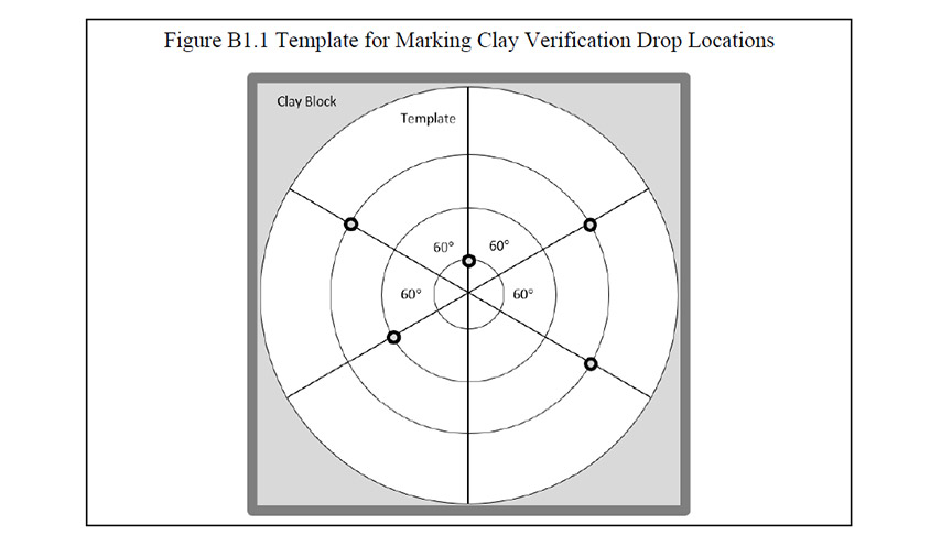
B.2 Modifications to ASTM E3004, Section 6.3, Clay Block Verification Procedure: Prior to Ballistic Testing
(1) Section 6.3.2.8 shall be replaced with:
Place the drop template on the clay surface in an arbitrary rotational position. Mark the surface of the clay block (for example, by nicking the surface, laser marking, applying ink) to indicate five drop target positions. Remove the template.
(2) Section 6.3.2.12 shall be replaced with:
Drop the impactor onto the clay block, ensuring the movable support does not move during the drop. The impactor shall be dropped five times, once on each of the marks on the clay surface.
(3) Section 6.3.2.13 shall be modified to require that the five indentation measurements be recorded.
(4) Section 6.3.3, Acceptance Criteria, shall not apply. The acceptance criteria shall be:
- The arithmetic mean of the five indentation depth measurements shall be 19.0 mm ± 2.0 mm (0.748 in ± 0.08 in).
- Each indentation depth measurement shall be 19.0 mm ± 3.0 mm (0.748 ± 0.12) .
- The measurements shall not be rounded off.
B.3 Modifications to ASTM E3004, Section 6.6, Clay Block Verification Procedure: Between Test Items
(1) Section 6.6, Clay Block Verification Procedure: Between Test Items, is required.
(2) Section 6.6.2.2 shall apply, with these additions:
Five drop target positions shall be marked on the clay surface, attempting to avoid placing drop target locations on the most recently repaired clay. Remove the template.
(3) Section 6.6.2.4 shall be replaced with:
Drop the impactor onto the clay block. The impactor shall be dropped five times, once on each of the marks on the clay surface.
(4) Section 6.6.2.5 shall be modified to require that the five indentation measurements be recorded.
(5) Section 6.6.3, Acceptance Criteria, shall not apply. The acceptance criteria shall be:
- The arithmetic mean of the five indentation depth measurements shall be 19.0 mm ± 2.0 mm (0.748 in ± 0.08 in).
- Each indentation depth measurement shall be 19.0 mm ± 3.0 mm (0.748 ± 0.12) .
- The measurements shall not be rounded off.
(1) Section 6.7, Clay Block Verification Procedure: After Final Shot on Clay Block is required.
(2) Section 6.7.2.1 shall apply, but the clay block shall be repaired.
(3) Sections 6.7.2.3 and 6.7.2.4, shall be replaced with:
Place the drop template on the clay surface in an arbitrary rotational position, attempting to avoid placing drop target locations on the most recently repaired clay. Mark the surface of the clay block (for example, by nicking the surface, laser marking, applying ink) to indicate five drop target positions. Remove the template.
(4) Section 6.7.2.5, shall be replaced with:
Drop the impactor onto the clay block. The impactor shall be dropped five times, once on each of the marks on the clay surface.
(5) Section 6.7.2.6 shall be modified to require that the five indentation measurements be recorded.
(6) Section 6.7.3, Acceptance Criteria, shall not apply. The acceptance criteria shall be:
- The arithmetic mean of the five indentation depth measurements shall be 19.0 mm ± 2.0 mm (0.748 in ± 0.08 in).
- Each indentation depth measurement shall be 19.0 mm ± 3.0 mm (0.748 ± 0.12).
- The measurements shall not be rounded off.
Appendix C: BFD Measurements
C.1 When any BFD measurement exceeds 44.0 mm, then there shall be a 95% confidence that 80% of all BFD depths will be 44.0 mm or less. This requirement can be verified using a statistical tolerance limit. It is expected that a stated portion of the entire population of all BFD measurements will lie at or below the statistical upper tolerance limit. To achieve this, the population of BFD measurements is assumed to be normally distributed, and the upper tolerance limit, BFDU, must be ≤ 44.0 mm. The upper tolerance limit is defined below:
Equation C.1: BFDu = BFDave + k1s
BFDave is calculated as shown below:
Equation C.2: BFDave = 1/NΣNi=1 BFDi
N represents the number of BFD measurements on a particular model, resulting from fair hits, and where the size, conditioning status, and test threat are the same. BFDi are the individual BFD measurements. The sample standard deviation, s, is calculated as shown below:
Equation C.3: s = √(1/N-1)ΣNi=1(BFDi-DFDave)2
The approximate k factor, k1, for a one-sided tolerance interval can now be calculated as shown below:
Equation C.4: k1 = z1-p+√(z21-p-ab)/a
Here, z1-p is the normal distribution-critical value that is exceeded with a probability of 1-p. The factors a and b are defined below:
Equation C.5: a = 1 − (z21-y)/(2(N-1)
Equation C.6: b = z21-p - (z21-y)/N
Here, z1-y is the normal distribution-critical value that is exceeded with a probability of 1-.
C.2 For the analysis of BFD measurements according to the requirements of this NIJ standard, the probability that no BFD measurement exceeds 44.0 mm must be at least 80%, so p = 0.80, and the required confidence is 95%, so =0.95. The critical values for the normal distribution can be calculated or obtained from tables in statistical textbooks. For this case, they are:
z1-y = z0.05 = 1.645; z1-p = z0.20 = 0.842
Table C.1 below provides some k1 values based on the number of BFD measurements.
Table C.1. k1 Values Based on Number of BFD Measurements
| Number of BFD Measurements | k1 |
| 12 | 1.568 |
| 13 | 1.528 |
| 14 | 1.494 |
| 15 | 1.464 |
| 16 | 1.438 |
| 17 | 1.415 |
| 18 | 1.394 |
| 19 | 1.375 |
| 20 | 1.358 |
| 21 | 1.342 |
| 22 | 1.328 |
| 23 | 1.315 |
| 24 | 1.303 |
Appendix D: Analysis of Ballistic Limit Data
D.1 Once the ballistic limit testing has been completed, the test results shall be analyzed for each test threat by performing a regression to estimate the armor model’s performance over a range of velocities. In particular, the analysis shall attempt to estimate the velocity where the probability of CP becomes reasonably small (i.e., V∧05 ≤ Vref). In general, a logistic regression can be used for this purpose; however, other probability distributions and regression methods may be used when one can be shown to better estimate the performance of a particular armor model.
D.2 The logistic regression may be performed on the data using the method of maximum likelihood to estimate the logistic parameters B∧0 and b∧1, which are the estimated logistic constant and the estimated velocity coefficient, respectively. These parameters define the shape of the S-shaped logistic curve, which is defined as:
Equation D.1: p(v) = (eb0+vb1)/(1+eb0+vb1)
Here, π(v) is the is the probability of a CP occurring at velocity, v. From the estimated logistic parameters, the ballistic limit can be determined as:
Equation D.2: V∧50 = (-B∧0)/b∧1
In addition, the velocity at which the probability of a CP is x%, V∧x, can be determined as:
Equation D.3: V∧x = (ln(x/1-x)-B∧0/b∧1
To determine the velocity at which the probability of a CP is 5%, V∧05, can be determined as:
Equation D.4: V∧05 = (ln(.05)-B∧0)/b∧1
Appendix E: Test Item Size Templates
E.1 This NIJ standard specifies five template sizes for testing soft armor test items:
1) NIJ-C-1 (smallest) as shown in Figure E.1.
2) NIJ-C-2 (small) as shown in Figure E.2.
3) NIJ-C-3 (medium) as shown in Figure E.3.
4) NIJ-C-4 (large) as shown in Figure E.4.
5) NIJ-C-5 (largest) as shown in Figure E.5.
E.2 The dimensions and shapes of the templates are shown in the figures on the following pages. The figures show red lines for the maximum test item dimensions and blue lines for the minimum test item dimensions.
E.3 The figures show the templates with and without a “neck scoop” at the top of each. The neck scoop indicates the front panel.
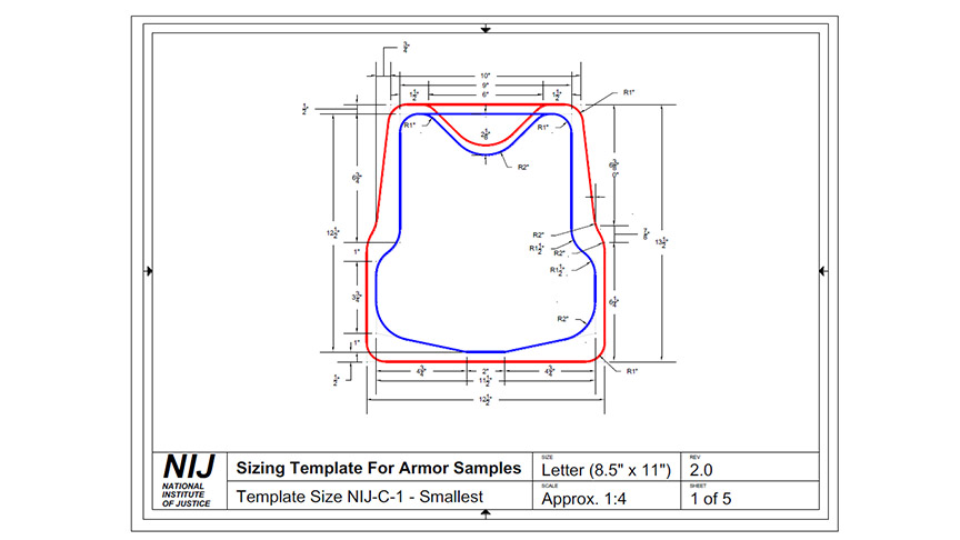
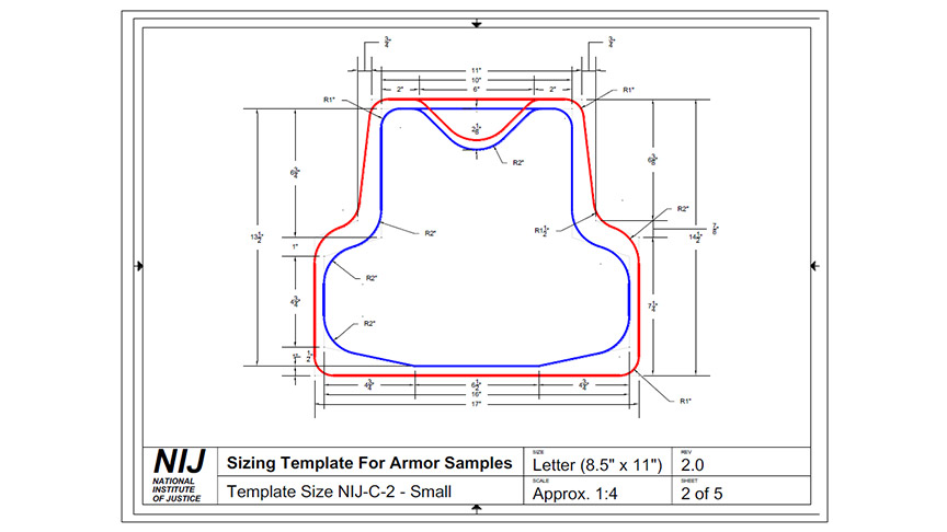
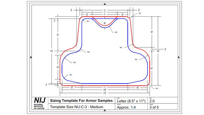
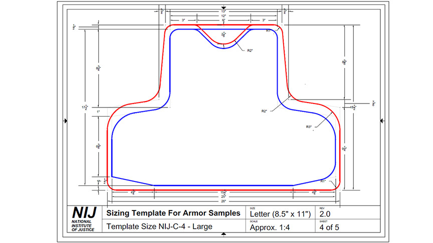
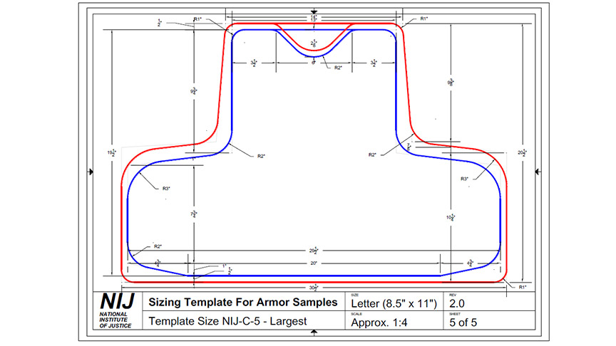
Appendix F: Label Requirements
F.1. Label Content RequirementsF.1.1. The label shall be permanently attached to the face of the test item. The label shall contain the following information (an example is provided in Figure F.1):
- Name, registered trademark or other identification of the supplier.
- The NIJ protection level.
- Reference to NIJ Standard 0101.07.
- A test ID number or model designation that uniquely identifies the armor design for testing purposes.
- The test item template size.
- A number or serial number that uniquely identifies each test item.
- Location of manufacture.
- Date of manufacture.
- Identification of the proper orientation of the armor panel (i.e., strike face or wear face).
- A warning in larger type than the rest of the type on the label that clearly emphasizes that the panel is a test item that has not yet been demonstrated to provide ballistic resistance and that the armor panel or plate is not intended to be worn. Printing color changes are acceptable but may not be substituted for the type size requirement herein.

Figure F.1. Example Label
F.2. Label System Tests for Permanency and Durability
F.2.1. Label System Test Items
F.2.1.1. The test item is the label system being evaluated. See Figure F.2 for a graphic of the label system and the required content to be included on the test item.
F.2.1.2. A total of five test items shall be subjected to testing. Two test items shall be tested in accordance with Section F.2.3, Resistance to Peeling Test; three test items shall be testing in accordance in Section F.2.4, Ink Permanency and Edge-of-Label Test.
F.2.1.2.1. To facilitate testing, the label assembly on the test items shall be affixed such that the long edges of the label assembly are near the edges of the substrate, as shown in Figure F.2.
F.2.1.2.2. If a clear laminate is present in the label assembly, its edge shall be less than 0.25 in (6.4 mm) from the long edge of the label.
F.2.1.2.3. The label itself shall be less than 0.5 in (13 mm) away from and parallel to the long edges of the substrate.
F.2.1.3. Special considerations for hard armor systems:
F.2.1.3.1. All substrate systems shall be nominally flat.
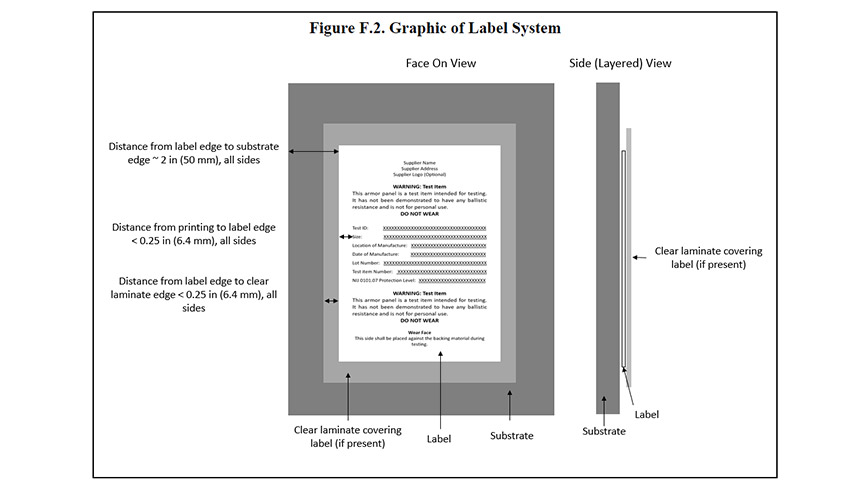
F.2.1.3.2. If the label substrate material is not a stand-alone material (e.g., spray liner or fabric wrap), then the manufacturer shall submit test items with representative substrates applied to a nominally planar surface (e.g., plastic, steel or wood). The surface finish of this material shall be representative of the surface finish that will be present in the finished product.
F.2.2. Visual Examination of Test Items
F.2.2.1. Visually examine each test item for imperfections. Imperfections include areas along the edge of the label or clear plastic laminate that are not in contact with the substrate or areas of the clear plastic laminate that are not in contact with the label.
F.2.2.2. Document any observed imperfections.
F.2.3. Resistance to Peeling Test
F.2.3.1. Quantity of Test Items
F.2.3.1.1. The test item is a label assembly.
F.2.3.1.2. Two test items are required.
F.2.3.2. Equipment and Materials
F.2.3.2.1. Packaging tape: Nominally 2-in wide, clear polypropylene tape with acrylic adhesive, adhesion to steel rating of 27 to 30 oz/in (30 to 34 g/mm).6
F.2.3.3. Procedure
F.2.3.3.1. Photograph the test item to document the pre-test condition.
F.2.3.3.2. Place the label assembly on a smooth, flat surface.
F.2.3.3.3. Adhere packaging tape lengthwise to the top surface of the label assembly. The adhered section must begin at the center of the label itself and extend to approximately 0.25 to 0.5 in (6 to 13 mm) beyond a side edge of the label assembly. Firmly press the tape as it is being applied. Allow extra length of tape to form a pull tab.
F.2.3.3.4. After waiting 60 seconds, hold the substrate down and use the pull tab, slowly pulling the packing tape by hand toward the label system center at a pull angle of approximately 45°, to remove the packing tape from the label assembly. See Figure F.3.
F.2.3.3.5. Document if any portion of the label assembly was removed from the substrate.
F.2.3.3.6. Photograph the test item to document the post-test condition.
F.2.3.3.7. The label assembly has failed this test if any of the label assembly is removed from the substrate.
F.2.3.3.8. In the event that the first label assembly fails, the test may be stopped.
F.2.3.3.9. Repeat the above steps on the second test item.
F.2.3.4. Test Report
F.2.3.4.1. The results from the peel test and any relevant observations shall be included in the test report.
F.2.4. Ink Permanency and Edge-of-Label Test
F.2.4.1. Test Items
F.2.4.1.1. Three test items are required.
F.2.4.1.2. Test items shall be cut from label assemblies to fit the rubber pad on the ink rub tester base, with the cut portion of the label as shown in Figure F.4.
F.2.4.2. Equipment and Materials
F.2.4.2.1. A Sutherland Ink Rub Tester (SIRT) or equivalent shall be used, with a test weight having mass of 4 lb ± 0.18 oz (1.81 kg ± 5 g), as specified in ASTM D5264. The speed during testing shall be 85 cycles per minute.
F.2.4.2.2. The receptor (in other words, abradant) shall be a swatch of nylon fabric, 200 Denier scoured only, off white color, that is sized to fit the test weight.
F.2.4.2.3. The preparation steps of ASTM D5264, Sections 10.1 through 10.7 shall be followed.
F.2.4.2.4. Two challenge fluids are required.
- Isopropyl alcohol: nominally 70% by volume; commonly available
- Water, oil, and soap mixture with the following formulation:
- 1 fl oz (30 ml) dish soap
- 1 fl oz (30 ml) mineral oil
- 18 fl oz water (532 ml)
F.2.4.3. Procedure
F.2.4.3.1. Photograph the test item to document the pre-test condition.
F.2.4.3.2. Place a test item onto the SIRT such that:
1) The test item is positioned on the ink rub testing apparatus such that the rubbing occurs on the face of the label in the long direction of the label.
F.2.4.3.3.1. When challenge fluid is being used, submerse the nylon abradant in the challenge fluid for at least 30 seconds prior to placing it on the test weight.
F.2.4.3.7. Photograph the test item to document the post-test condition.
F.2.4.3.8. In the event a test item fails, the test may be stopped.
F.2.4.3.9. Repeat the above steps for the remaining test items.
Appendix G: Guidance for P-BFD Testing of Soft Armor Designed for Female Wearers
G.1 Location of Shaping Features
G.1.1 Using the supplier-provided dimensioned diagram, locate on each test item the stitches, seams, folds, and other shaping features. If overlaps of material exist in the test item, the direction of overlap of the subcomponents of the test item shall be documented. These features shall be marked on the test item panel cover.
G.2 P-BFD Shot pattern (i.e., shot location, angle, and direction) marking
2) The shot patterns listed in Table G.1 shall be followed unless modification is necessary to exploit potential areas of weakness.
3) Typically, the shot pattern for the first test item will follow the guidance provided below. The shot patterns for subsequent test items should be modified as necessary based on observed results.
Table G.1. Shot Pattern Summary Table for Test Items with Stitch Patterns (i.e., Darted and Princess Cut) Forming Bust Cups
| Shot # | Larger test item 1 Smaller test item 2 | Larger test item 2 Smaller test item 4 | Larger test item 3 Smaller test item 6 | Larger test item 3 Smaller test item 6 |
| Shot 4 |
|
|
|
|
| Shot 5 |
|
|
|
|
| Shot 6 |
|
|
|
|
G.3.1.1 Placement of shots 1, 2, and 3 (i.e., edge shots) should avoid seams or areas of overlap, while meeting the shot spacing requirements of ASTM E3107. For each test item, shots 1, 2, and 3 shall meet the shot-to-edge distance requirements but shall be located not more than the shot-to-edge distance plus 0.75 in (19 mm) from the edge of the test item.
G.3.1.1.1 These shots shall be moved to different locations within the shaded band shown in Figure G.1. The light gray band applies to the greater mass test threat, and the dark gray band applies to the lesser mass test threat.
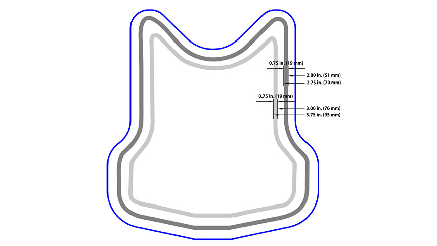
G3.1.2.2 Placement of shot 4
a) First test item of a given size
i) Shot 4 shall be used to challenge the apex of either the left or right bust cup.
ii) For hybrid designs where multiple stitch patterns are used throughout the layup, the strike face stitch pattern shall be used to determine shot placement.
iii) The overlap on the strike face shall be identified, and shot 4 shall be angled into the overlap seam. See Figure G.2 for placement of shot 4 with respect to the overlap. See Figure G.3 for examples of shot placement in regions of horizontal overlap.
b) Second test item of a given size
i) Shot 4 on test item 2 shall challenge the other bust cup apex.
ii) The same modifications listed in Section G.3.1.2.2, a) for vertical and horizontal seams shall be followed.
c) Third and fourth test items of a given size
i) For test items where this position represents an overlap in material, the shot shall be offset to the nearest point on the test item where no overlap exists.
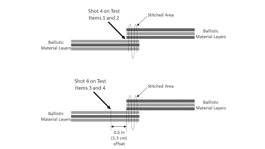
a) Shot 5 shall be placed according to ASTM E3107, Section 11.2, following the surface of the test item. Shot 5 shall be shifted slightly to avoid placing shots 4 and 5 along the same vertical or horizontal lines while adhering to the 3.94 in (100 mm) diameter circle.
b) The location for shot 5 may be altered by rotating around the shot 4 location.
c) Ensuring that shot spacing requirements are met, the location of shot 5 should not be on an overlap where possible but may be adjacent to or offset from an overlap.
d) Shot 5 shall be taken in the same direction as shot 4.

G.3.1.2.4 Placement of shot 6
a) For the first test item of a given size in the test series, shot 6 shall be placed according to ASTM E3107, Section 11.2, following the surface of the test item.
(2) Smaller shaping mold (for conforming the clay appliques to the shape of the test items)
(3) Larger applique mold
(4) Larger shaping mold
(2) Select Roma Plastilina #1 clay that has been temperature conditioned for a minimum of 3 hours in a chamber having conditions as specified in ASTM E3004.
(3) Place a layer of thin plastic wrap, or similar material, into the applique mold to assist with removal of the applique from the mold.
(4) Work the conditioned clay into the applique mold until the mold is completely filled and no voids are present. If necessary, use a draw knife, or similar device, in contact with two parallel edges of the mold to strike the clay to create a planar surface.
(5) Remove the clay applique from the mold, keeping the plastic wrap attached to the applique.
(6) Position the test item, wear face up, on the shaping mold and place the applique on the wear face, matching the appropriate face of the applique to the test item.
(7) Using a uniformly shaped (not tapered) cylinder as a rolling pin, roll the applique into the test item so that the clay conforms to the shape of the test item.
(8) Remove the applique and test item from the shaping mold.
(9) Separate the applique from the test item.
(10) Place the applique on the conditioned clay block with the flat side against the clay block. Remove the plastic wrap from the applique.
(11) Hand form warm clay into a long, thin strip. Place the strip around the perimeter of the applique at the interface with the clay block and press the clay strip into the interface to ensure that the applique remains adhered to the clay block during testing.
NOTE: Care is required to ensure that the shape of the applique is not significantly changed while affixing it to the clay block.
(12) Place the test item on the applique, aligning the test item appropriately with the shape of the applique.
Appendix H. Flowcharts for Testing
About Standards and Conformity Assessment at the National Institute of Justice
NIJ standards and conformity assessment activities are conducted by NIJ’s Office of Technology and Standards (OTS). OTS works to identify the needs of state and local criminal justice system practitioners for equipment standards and test protocols, develops voluntary performance standards for specific criminal justice tools and technologies, establishes conformity assessment requirements for demonstrating that commercially available equipment conforms to those standards, and publishes listings of product models that have been tested through one or more specified organizations and found to comply with the standards.
The standards development process begins with gathering the operational needs and requirements of practitioners in the field. Based on those needs and requirements, the standards are developed in coordination with a special technical committee composed of criminal justice practitioners, testing experts, other technical experts, federal partners, and members from practitioner-stakeholder organizations. Manufacturers, vendors, and other interested parties are provided with an opportunity to review and comment on draft standards prior to their publication.
All NIJ standards are voluntary standards. There is no requirement or obligation for manufacturers, law enforcement or corrections agencies, or others to follow or adopt these voluntary law enforcement technology equipment standards. The primary intent of these standards is to provide end users and equipment producers with performance criteria on equipment characteristics and allow comparison of product models based on standardized testing methods and performance requirements. These standards do not specify a particular solution but rather define what a potential solution must accomplish. Conformity assessment based on NIJ standards, such as testing and certification, provides a level of confidence in that particular model’s fitness for use in specified circumstances. The ultimate goal is to help ensure, to the degree possible, that law enforcement and corrections equipment is safe, reliable, and effective.
NIJ’s standards and conformity assessment activities are responsive to provisions in the Homeland Security Act of 2002 that authorize NIJ to establish and maintain performance standards (in accordance with the National Technology Transfer and Advancement Act of 1995) for law enforcement technologies that may be used by federal, state, and local law enforcement agencies, and to test and evaluate those technologies. The Homeland Security Act of 2002 also authorizes NIJ to establish and maintain a program to certify, validate, and mark or otherwise recognize law enforcement technology products that conform to the standards mentioned above.
NIJ standards, including this standard, are available at no charge online at https://nij.ojp.gov/active-nij-standards-and-comparative-test-methods. Users of NIJ standards are advised to check that page regularly to determine whether a particular law enforcement technology equipment standard has been revised or superseded, or if the compliance status of a particular model has changed as applicable.